Generally, a robot must have sensory input similar to or superior to the human senses in order to replace or serve as extensions of humans in dangerous, delicate, or remote applications. Especially in dexterous manipulation tasks, robots require tactile perception of objects through mechanical contact. Thus, measurement and processing of contact force information is also of great importance in robotic dexterous manipulation. When a human fingertip comes into contact with an object, a contact force profile has three components: one component oriented normal to the surface, and the others oriented tangential to the surface. The force profile provides humans with rich sources of information about their physical environments. The shear load is especially important from the viewpoint of slip detection between a fingertip and object. Shear force information is useful in dexterous robotic manipulation. For example, shear information is required for full grasp force and torque determination, especially when grasp forces are in the range of 0.01 N - 0.1 N, where fingertip force-torque sensors are ineffective. In addition, measuring shear force enables prediction and determination of object slip, as well as estimation of the static coefficient of friction [1-4].
On the other hand, some researchers have recently developed micro-electro-mechanical system (MEMS)-based tactile sensors. A lot of work has focused on silicon based sensors that use piezoresisitive [5] or capacitive properties [6]. Actually, the silicon substrate used for micomachined tactile sensors presents fundamental limitations. The silicon is mechanically brittle and rigid, so it is incapable of sustaining large deformation and sudden impact. Thus, it is difficult to form a continuous and conformal tactile sensor that can be used to cover contoured surfaces. Recently, a polymer-based tactile sensor was proposed, but the sensor mainly measures only normal loads [7-9]. To apply a robotic fingertip, the miniature polymer-based three-axial tactile sensor is a possible solution.
In this paper, we present the design and fabrication of the polymer-based, three-axial tactile sensor for robotic fingertips. Conventional polyimide film is used for the substrate of the tactile sensor. Four strain gauges are positioned independently in order to measure the three-component loads against applied loads. Finally, the sensor test is carried out using the evaluation system with a three-component load cell.
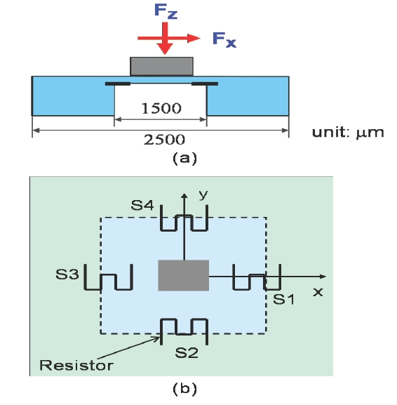
We designed a three-axial tactile sensor as shown in Fig. 1. In order to obtain maximum sensitivity, regions of high stress were identified and the dimensions and positions of strain gauges were determined accordingly. An external force applied to the sensor can be resolved into its three-components x, y, and z as shown in Fig. 1(a). The total size of the sensor is 2.5 mm by 2.5 mm, and the membrane's thickness and size are 50 μm and 1.5 mm × 1.5 mm, respectively. The thickness of the membrane has been decided such that the force capacity of the sensor is equivalent to the maximum load for the sensor to be applied in the robotic fingertips. On the other hand, a Dupont Kapton HN200 polyimide sheet with a thickness of 125 μm was used as the substrate of the sensor. The schematic diagram of the designed sensor with four strain gauges (S1~S4) is shown in Fig. 1(b). The bump is a column type with the square of 600 μm by 600 μm. Meanwhile the bump and the supporting block are assumed as a rigid body due to greater thickness compared with the thin membrane.
The commercial finite element program ANSYS version 5.7 (ANSYS INC., Canonsburg, PA, USA) is used to design the sensor [10]. The used material is polyimide that has an elastic modulus of 3.4 GPa, ultimate stress of 190 MPa, and Poisson's ratio of 3.3. We use the finite element model that consists of the shell element with four nodes. The supporting block of the sensor except for the membrane with thickness of 50 μm is constrained at the bottom. The normal load Fz is applied uniformly to the upper surface of the bump. Each shear load (Fx, Fy) is applied uniformly to the lateral face of the bump, respectively. The maximum force applied to the sensor is 0.8 N.
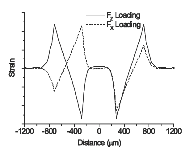
The position of strain gauges has been acquired from the finite element analysis (FEA) results as shown in Fig. 2. It shows the strain distribution along the centerline of the membrane when each maximum load is applied in the x and z directions, respectively. In the case of normal loading, the strain distribution along the x-axis of the membrane shows symmetric distribution with respect to the y-axis. The inclination of strain is negative up to 730 μm from the membrane center, and positive up to 770 μm from the membrane periphery. Meanwhile, when a shear load Fx is applied to the bump, the strain distribution along the centerline indicates the asymmetric inclination with respect to the origin point. Using these strain distribution values, the shape and size of the strain gauge are determined in order to maximize the sensitivity of the sensor. When a strain gauge is located around the membrane periphery, the average normal strain of the strain gauge is 4,500. Meanwhile the average shear strain is 1,000 when the Fx load is applied. Thus, the ratio of the sensitivity of the normal load to that of the shear load is 4.5. From the FEA results, it is clear that the strain gauges positioned at the periphery of the membrane have maximum sensitivity.
3. SENSOR FABRICATION AND SIGNAL ACQUISITION
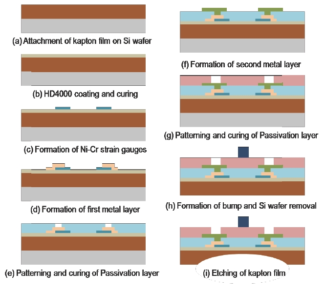
The fabrication process of the flexible three-axial tactile sensor is summarized in Fig. 3 [11,12]. The substrate used in this experiment is the DuPont Kapton HN ployimide film with a thickness of 125 μm. A sheet of Kapton polyimide film is attached to a 6-inch standard silicon wafer, as shown in Fig. 3(a). The film anchored to the silicon wafer is convenient for subsequent processes like conventional MEMS fabrication. In order to smooth the surface of the polyimide film, a conventional polymer with thickness of 3 μm is spun on the top surface of the polyimide film, and then cured at 350℃ for 2 hours, as shown in Fig. 3(b).
Next, nichrome (Ni:Cr = 8:2) is used in the strain gauges due to its high resistivity and low coefficient of thermal resistance. A nichrome layer with thickness of 2,000 Å is defined on a Cr adhesion layer using e-beam evaporation and the lift-off method, as shown in Fig. 3(c). Au input lines with thickness of 2,000 Å are patterned using the same process as for the strain gauge step, as shown in Fig. 3(d). Before the deposition of each metal, the film is treated with oxygen plasma at 60℃ and 100 W for 2 minutes to improve adhesion and remove photoresist residues.
The first passivation layer is then spun on, patterned, and cured using photo-definable polyimide (HD4104; HD Microsystems, Parlin, NJ, USA), and its thickness is 3 μm, as shown in Fig. 3(e). The HD4100 series polyimide is chosen because it is solvent developed and photo-definable. The inclination of the open window is very important to connect between the output pads of the strain gauge and output metal lines. To define the inclination of the first passivation layer, an exposure gap of 300 μm is kept during the exposure process. Au output lines with thickness of 3,000 Å are deposited on the first passivation layer using the previous metal deposition method, as shown in Fig. 3(f). In order to protect the metal layer and define the contact hole, the second passivation layer is defined by the same method and material as the first passivation layer, as shown in Fig. 3(g). The bump is patterned to apply normal and shear loads using multiple spin coating of photo-definable polyimide, as shown in Fig. 3(h). The height of the bump is 50 μm, and its size is 600 μm × 600 μm.
After removal of the silicon wafer, the backside of the Kapton film is etched to define the diaphragm. SU-8 photoresist with thickness of 15 μm is used as an etching mask for the film. SU-8 is selected as an etching mask because it does not dissolve in etching solution as do conventional photoresist and polymer. The etching solution for wet etching of the Kapton film consists of potassium hydroxide (KOH), ethanol, and de-ionized water. After etching at 70℃ for 15 minutes, the membrane with thickness of 50 μm is defined, as shown in Fig. 3(i). The etching mask is removed easily by bending polyimide because SU-8 is very brittle.
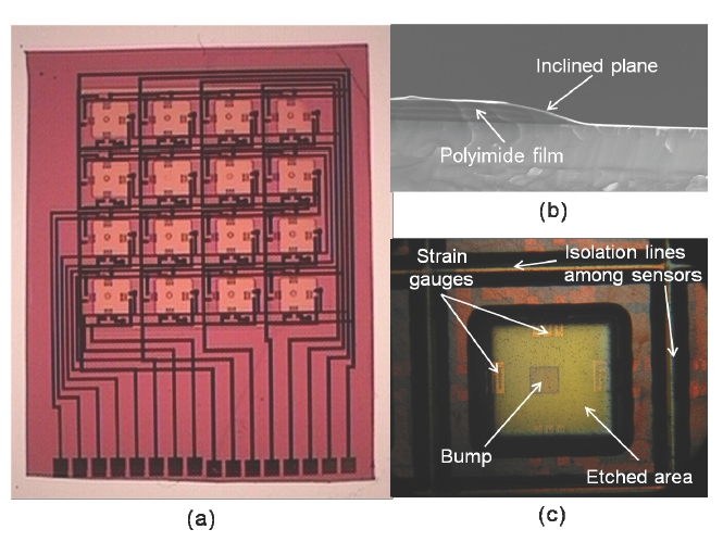
Figure 4(a) presents the photography of the fabricated flexible tactile sensor array, which is composed of sixteen tactile sensors. The inclination of the first passivation layer is shown in Fig. 4(b). It shows that the output pads of strain gauge and output lines can be connected without electrical opening because the open window of the first passivation layer has a gentle inclination. Figure 4(c) is the backside photograph of a tactile sensor. It shows a bump and four strain gauges on the opposite side, and has a well-defined etching profile. For easy attachment to the robot fingertip, isolation lines are defined. They are wet-etched with the diaphragm at the same time.
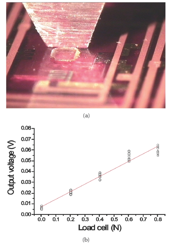
The completed tactile sensor is evaluated using the evaluation system that has the rated capacity of +/-10 N in three-component force, as shown in Fig. 5. The system has a universal stage that makes three-component loadings: Fx, Fy, and Fz. The forces are applied to the sensor by rotating the three-axis of the stage. The three-component loadcell and the tactile sensor are connected to a signal conditioning amplifier (DMC9012A; HBM Co., Darmstadt, Germany) and multimeter (3458A; Agilent Co., Santa Clara, CA, USA), respectively.
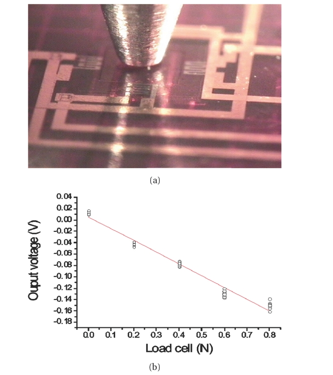
Testing of the sensor is carried out using an evaluation system. The data of the normal load are acquired when an applied force increases from 0 N to 0.8 N along the z-direction, as shown in Fig. 6(a). The responses of the sensor according to application of the normal load are plotted in Fig. 6(b). The sensor is loaded and unloaded eight times to generate the data. The slope of the output voltage is obtained by using the least square method. Sensitivity is found to be about 206.57 mV/N, with good linearity (coefficient of determination, R2 = 0.9819). When the test is carried at 0.8 N, the response becomes less linear. The fabricated sensor is saturated at 0.8 N. That is why its capacity is 0.6 N.
The shear load test is carried out when an applied force varies at the same rate as the normal load along the x-direction, as shown in Fig. 7(a). The responses of the sensor to shear displacement are shown in Fig. 7(b). It has a sensitivity of 70.1 mV/N and good linearity (coefficient of determination R2 = 0.9821). On the other hand, Figs. 6 and 7 show that the normal load is 3 times more sensitive than the shear load. This is the reason why two strain gauges (S2, S4) are not significantly influenced during the force is applied along x, and y directions respectively.
The test of the sensor array according to the applied force was not presented in this paper because each sensor showed different results. Because the Kapton polyimide film was contracted during the curing process, the positions of the etched diaphragm and bump shifted irregularly. After the Kapton polyimide film was released from the silicon wafer, alignment for photolithography photolithography was not matched. We have a plan to fabricate sensors with uniform properties by analyzing the contraction rate of Kapton polyimide film during the fabrication process. We are going to introduce the responses about the flexible sensor array in the next paper.
The flexible three-axial tactile sensor was designed and fabricated, and its size was 2.5 mm × 2.5 mm. The sensor has a square membrane, and its force capacity was 0.6 N in the three-axis direction. The advanced polyimide microfabrication technology was used to fabricate the three-axial tactile sensor. In order to confirm the characterization of the sensor, it has been evaluated by applying normal and shear loads from 0 N to 0.8 N using the evaluation system with the three-axial loadcell. The sensitivities of normal and shear loads were about 206.6 mV/N and 70.6 mV/N with a linearity of 0.982, respectively. The test showed that the sensor can measure normal and shear loads simultaneously when touching objects. The experiments further enlarge the possibility that robots can have grasping ability using the demonstrated three-axial tactile sensor.