When dealing with large scaled, high voltage rotating machines that are small and light weight, such as generators and motors, the increase in power generation and development of technology has emphasized the troubles caused by failures in the insulation. A large part of the fault in a rotating machine is presented by damage in windings, and the most important part of insulators is stator windings [1].
The insulation material used in high voltage rotating machines can be degraded due to various factors (thermal, electrical, mechanical, and environmental), and the degradation caused by insulation breakdown causes accidents. An accurate diagnosis for insulation degradation in windings needs to be performed in order to achieve economical operations based on optimal maintenance. A lot of studies on the technology that measures PD generated in winding insulations have been conducted in order to find a good diagnosis method [2].
In the case of PD, voltages and current pulses are generated, and these discharge sparks generate RF electromagnetic waves, which are transmitted from the discharge point. The electromagnetic wave generated by PD has an RF frequency ranging from 100 kHz to hundreds of MHz. It is possible to detect the electromagnetic wave using a single sensor that shows excellent detection sensitivity and a wide detection range as the electromagnetic pulse is generated from such PD [3], [4].
In this study a planar patch sensor was designed to measure the RF electromagnetic wave generated from a PD located at stator windings in a rotating machine. PD was measured with the stator windings with artificial defects using both the planar patch sensor and a HFCT (High Frequency Current Transformer) sensor in the same PD measurement system. The frequency characteristics were measured with a spectrum analyzer and were analyzed in order to compare the detection performance of these two sensors.
The patch sensor was a type of microstrip that showed a change in its characteristics in accordance with various feeding methods and patch types. A planar patch sensor is a type of microstrip patch antenna that has an earth ground under the regular circuit boards and microstrip feeding lines over the boards. The metal foil patch and the earth ground are separated by dielectric materials. The most important factor that determines the performance of a planar patch sensor is the thickness of dielectric materials. It is possible to obtain a desirable efficiency, a wide bandwidth, and a small space radiative loss by reducing the permittivity.
The matching characteristics between the feeding and the radiation parts can be controlled by the width of the feeding microstrip lines and feeding distance, and impedance matching can be implemented using following equations [5], [6].
The resonance frequency of the structure can be determined by Eq. (1).
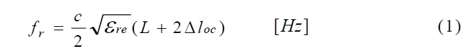
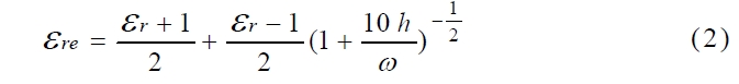
Where c is the velocity of light, L is the length of the patch, and are is the effective permittivity of the microstrip as presented by Eq. (2).
The radiative resistance of the patch is expressed by Eq. (3).
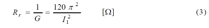
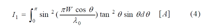
Where I1 can be defined as an integration as noted by Eq. (4).
The characteristic impedance of the microstrip transmission lines is then determined by Eq. (5).
[Table 1.] The parameters of the planar patch sensor.
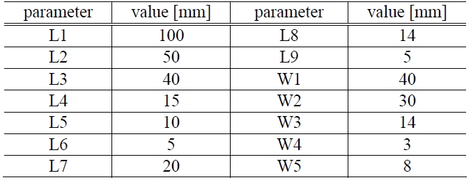
The parameters of the planar patch sensor.
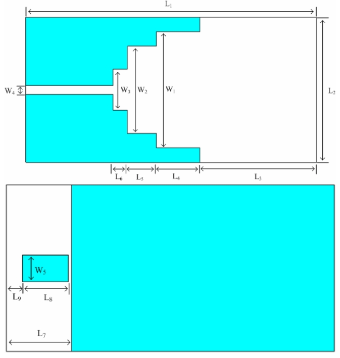
Figure 1 shows the geometry of the planar patch sensor proposed in this study. In the fabrication of the planar patch sensor, a FR-4 board that had a permittivity of 4.6 and a width of 1.6 mm was used. As shown in Table 1, the distance between feeding parts (W4) was 3 mm, the patch had a wid stair shape, and the length of the earth ground (L7) was 20 mm.
The fabricated planar patch sensor was designed using the results of the simulation performed by the CST-MWS (Computer Simulation Technology Microwave Studio) program.
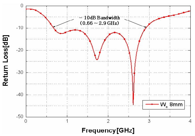
In the results of the simulation performed by using the parameters mentioned in Table 1, the return loss of the sensor was varied according to the shape of the patch and the ground type. The resonance frequency band showed the largest value as the length of the ground was determined to be 8 mm after determining the shape of the patch.
Figure 2 illustrates the simulation’s return loss for the designed planar patch sensor. It shows the maximum output of the return coefficient to have a bandwidth of 2.9 GHz. This wide-band characteristic includes the frequency range of electromagnetic waves generated by PD.
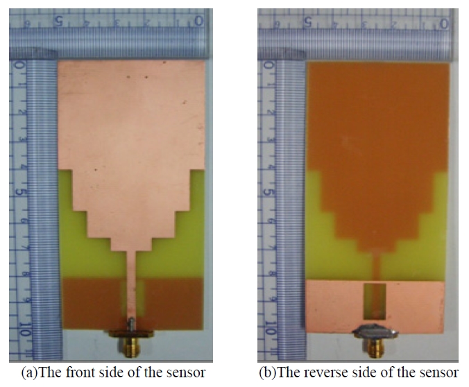
Figure 3 shows the actual figures for the fabricated sensor the size of which was 5 x 10 cm.
Voltage was applied to the 6.6 kV rotating machine stator winding that had simulated faults for slot discharges, internal discharges, and surface discharges. The PD signals were measured using both the planar patch sensor and HFCT sensor.
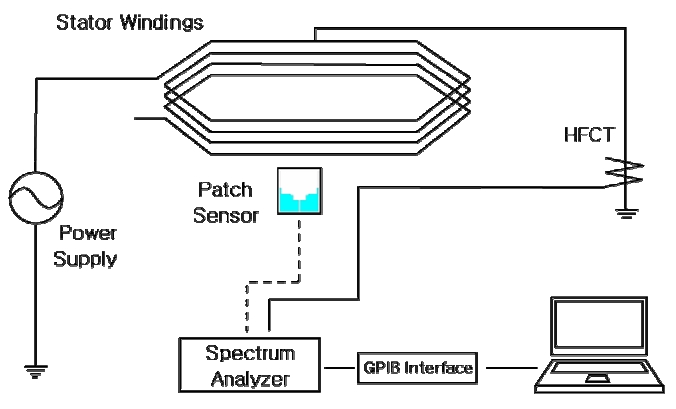
As illustrated in Fig. 4, the PD measurement system consisted of a power supply system (Tektronix), a spectrum analyzer (Agilent, N93 -20 A, 9 kHz∼3 GHz), a notebook PC, the planar patch sensor (0.66∼2.9 GHz), and a HFCT (0∼50 MHz) sensor. In the measurement method used by the patch sensor, the measurement was performed at a distance of about 5 cm from the stator winding in order to measure the electromagnetic wave radiated from the fault sections. The HFCT sensor was attached to the earth line of the stator winding in order to measure the pulse currents caused by the PD.
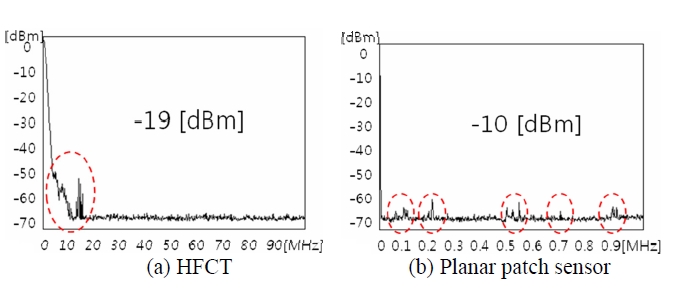
The external noise was measured as shown in Fig. 5 without applying any voltage to the stator winding in order to measure the background noise present in the HFCT and the planar patch sensors. The external noise detected in the HFCT sensor below 15 MHz ranged up to -19 dBm. In the case of the patch sensor, external noise was detected up to -10 dBm at the bandwidths of 50∼100 MHz, 170∼220 MHz, 480∼540 MHz, and 870∼900 MHz.
In general, although the signal detection bandwidth in the sensors showed different values, this study investigated the performance of the detection of PD signals by measuring the signals using the commonly used HFCT sensor and the fabricated planar patch sensor.
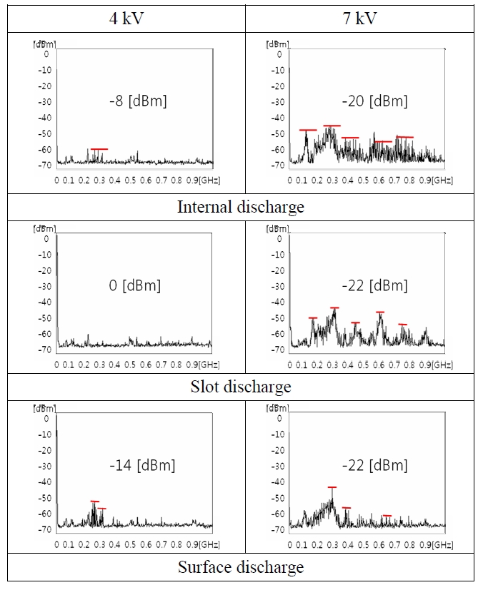
The stator winding with the simulated faults had a PD starting at a voltage of 4 kV. The measurement sensitivities of the two sensors were compared by applying the maximum voltage of 7 kV.
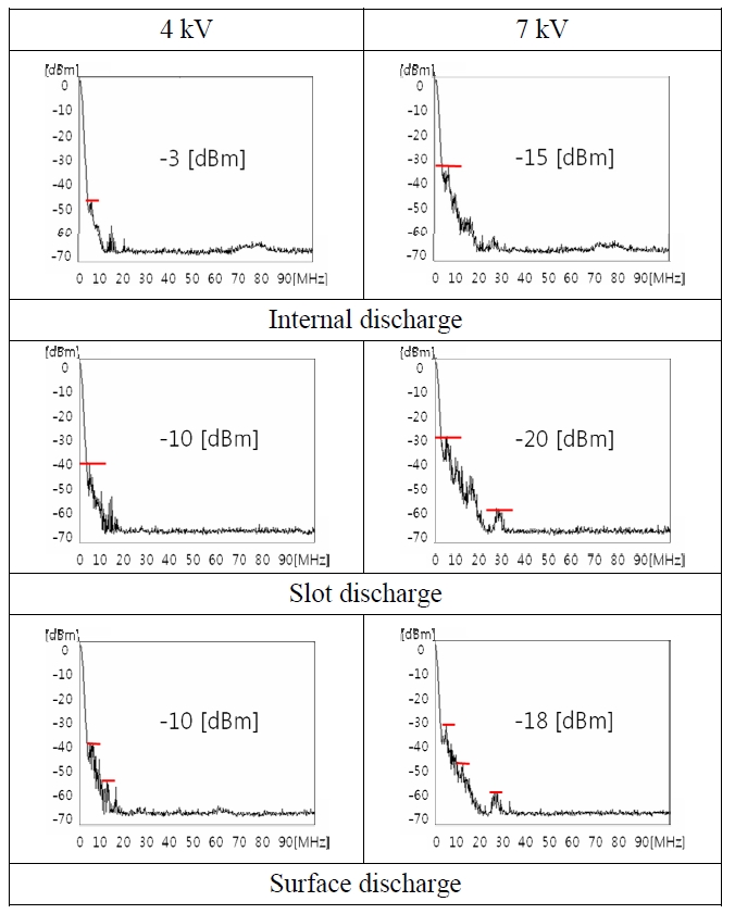
Figure 6 shows the results of the measurement of the HFCT sensor. In the stator winding that had the simulated internal discharge faults, the discharge signal increased up to -3 dBm at bandwidth below 10 MHz when a 4 kV signal was applied, and had a maximum -15 dBm discharge signal measured at a bandwidth below 30 MHz when 7 kV was applied. In the cases of the slot discharge and the surface discharge, the signal was measured at -10 dBm a bandwidth below 10 MHz when 4 kV was applied. The discharge signals were measured at -20 and -18 dBm, respectively, when 7 kV was applied.
[Table 2.] The PD measurement results
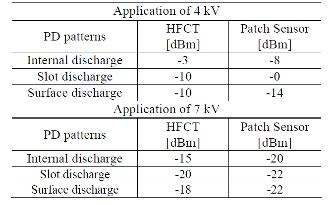
The PD measurement results
In the case of the planar patch sensor, the internal discharge signal was detected up to -8 dBm as a voltage of 4 kV was applied, and the signal increased by up to -20 dBm at the bandwidths of 100∼1000 MHz as a voltage of 7 kV was applied. Also, the discharge signal was detected at a bandwidth below 900 MHz in line with the increase in voltages. In the case of the slot discharge, the discharge signal was detected at up to -22 dBm at a bandwidth below 900 MHz when a voltage of 7 kV was applied. In the case of the surface discharge, the discharge signal was detected up to -14 dBm at bandwidths of 200∼300 MHz when 4 kV was applied. These results of the experiments showed a similar performance to references [3], [4].
When comparing the results of the measurements using these two sensors, the patch sensor showed a higher sensitivity than the HFCT sensor. In particular, the patch sensor showed a bit Higher signal value than the HFCT sensor did under the discharge starting voltage. In addition, it was verified that the planar patch sensor can detect PD signals at a wide bandwidth because it has a wide band detection range.
Wide band planar patch sensor measured the PD signals ranged from 100 kHz to 1 GHz in rotating machine stator windings. These results are compared with the detection performance using the HFCT sensor through measuring artificial defects. The HFCT sensor detected the discharge signal at a maximum of -20 dBm at a bandwidth below 30 MHz, and the planar patch sensor detected the signal at a maximum of -22 dBm at a bandwidth below 1 GHz. In the comparison of these two sensors, the planar patch sensor showed a larger value of about 2∼5 dBm for internal, slot and surface discharges than those of the HFCT sensor. The planar patch sensor was able to detect discharge signals without any noise limitations. Thus the planar patch sensor can be usefully applied to verify initial defect because it showed a better detection performance than the HFCT sensor.