Respiratory signals often provide important indications about the psychological and physical condition of a patient. In clinical or high risk situations, it is necessary to measure the respiration of the patient during surgical procedures inside a magnetic resonance imaging (MRI) system [1-4]. However, monitoring of respiratory activity such as respiratory rate, depth and gas exchange in an MR room with conventional electrical sensors or transducers is challenging, as the strong gradients of magnetic fields and the radiofrequency (RF) pulse induce interactive noise on the physiological signals during MR image acquisition. Thus, it is necessary to develop medical devices that can monitor the respiratory signal with other biomedical signals such as temperature and photo-plethysmograph (PPG) even in the presence of strong electro-magnetic interference [5-10].
One potential solution is the use of a fiber-optic sensor made of dielectric materials to minimize distortion of the MR image. Optical fiber-based sensors offer numerous advantages over conventional sensors such as absence of electrical interference, fast response time, good flexibility and remote sensing [11-17]. The use of fiber-optic sensors instead of electrical devices can reduce electro-magnetic disturbance of the magnetic field as well as burning hazard to the patient inside the MRI system. In general, respiratory activity can be detected by utilizing differences of temperature, humidity and carbon dioxide (CO2) of respiratory airflow and variations of thoracic or abdominal circumferences [18-21].
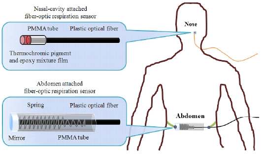
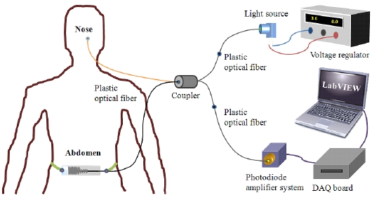
In this study, we have fabricated nasal-cavity and abdomen attached fiber-optic respiration sensors for noninvasive respiratory monitoring. Using these two types of non-invasive fiber-optic respiration sensors, we have measured the respiratory signals of a patient during imaging in an MRI system, as illustrated in Fig. 1, and the respiratory signals of the fiber-optic respiration sensors are compared with those of conventional respiration transducers.
II. MATERIALS AND EXPERIMENTAL SETUP
In this study, we have fabricated two types of fiber-optic respiration sensors, as shown in Fig. 2. The fiber-optic respiration sensors are composed of plastic optical fibers, a respiration sensing part, a light source and a photodiodeamplifier system. The plastic optical fiber chosen for these respiration sensors is a step-index multi-mode fiber (Mitsubishi Rayon GH-4001). The outer diameter of this optical fiber is 1.0 mm, and the core diameter is 0.98 mm. The refractive indices of the core and the cladding are 1.490 and 1.402, respectively, and the numerical aperture (NA) is about 0.5. The materials of the core and the cladding are polymethyl-methacrylate (PMMA) and fluorinated polymer, respectively, and the jacket is made of polyethylene (PE).
The first of the two sensors is a nasal-cavity attached fiber-optic respiration sensor that can measure the air-flow using a thermochromic pigment (En-tech Polymer Chameleon-T P-Red 31), which has a reversible characteristic whereby its color changes according to the temperature. At room temperature, the color of the thermochromic pigment is red, but the pigment loses its color by absorption of heat above 31℃. The respiration sensing part of the nasal-cavity attached fiber-optic sensor is composed of a temperature sensing film, a PMMA tube and a plastic optical fiber. The temperature sensing film is fabricated by mixing thermochromic pigment powder and epoxy resin at a 1:20 mass ratio. The thickness of the film is 0.01 mm. The temperature change in the respiration sensing part, which is situated in the nose, gives rise to a color change of the temperature sensing film. During inhalation, the film color of the nasal-cavity attached fiber-optic respiration sensor is red, but its color changes to white due to the warm expiratory air during the exhalation period.
The second of the two sensors is an abdomen attached fiber-optic respiration sensor that can measure change of the abdominal circumference due to respiratory movement. The respiration sensing part of this sensor is composed of a PMMA tube, a protected aluminum mirror (Thorlabs PF10-03-G01), a spring and a plastic optical fiber. The intensity of reflected light is changed by the variation of the distance between the mirror and the distal end of the plastic optical fiber according to abdominal movement.
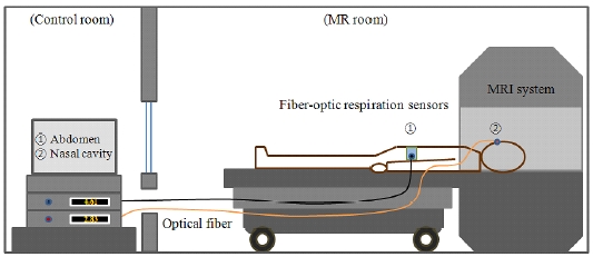
Figure 3 shows the experimental setup for measuring the respiratory signals. As a light source, a green LED (Industrial Fiber Optics IF-E93) is used. The peak wavelength and full width at half maximum (FWHM) of the LED is 530 nm and about 50 nm, respectively. An internal microlens and the plastic housing of the light source ensure efficient optical coupling with a plastic optical fiber of 1.0 mm diameter. The plastic optical fiber was connected to a Si-photodiode (Hamamatsu Photonics K.K. S1336-18BK) and an amplifier system, which are located outside the MR room. The photodiode-amplifier system is fabricated so as to obtain a large signal-to-noise ratio (SNR) with simple electronics. A Si-photodiode, whose usable wavelength ranges from 320 to 1,100 nm with a peak wavelength of 960 nm, is used as an optical measuring device.
The emitted light from the green LED is guided by a 10 m plastic optical fiber and a 1 m fiber-optic coupler (Mitsubishi Rayon IF-562), which has a 50:50 splitting ratio to each respiration sensing part. The intensity of the reflected light is changed by variation of the optical property at the respiration sensing parts, and the light is guided to the Si-photodiodes via a plastic receiving fiber. Therefore, we could measure the intensity of the modulated light, which is changed due to the air-flow and abdominal movement, respectively, via the homemade photodiodeamplifier system.
III. COMPARISON OF THE RESPIRATION SIGNALS USING A CONVENTIONAL SENSOR
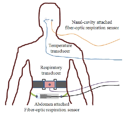
The experimental setup for comparison of the respiratory signals using the proposed fiber-optic respiration sensors and a BIOPAC® system (BIOPAC Systems MP 30B-CE) is illustrated in Fig. 4.
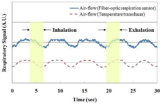
Figures 5 and 6 compare the comparisons of the respiratory signals due to the stimulated breathing, which are obtained using the fiber-optic respiration sensors and the BIOPAC® system simultaneously. In Fig. 5, the respiratory signals of the nasal-cavity attached fiber-optic respiration sensor and a temperature transducer (BIOPAC Systems SS6L) are maintained uniformly by the ambient temperature during inhalation, but they increase during the exhalation period due to the warm expiratory air.
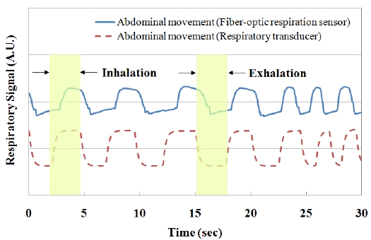
On the other hand, the respiratory signals of the abdomen attached fiber-optic respiration sensor and a respiratory transducer (BIOPAC Systems SS5LB) increased during the inhalation period, and decreased with a decrease of the abdominal circumference during exhalation, as shown in Fig. 6. Therefore, we have demonstrated the similarity of the respiratory signals between the fiber-optic respiration sensors and the transducers of the BIOPAC® system.
IV. TEST OF THE MR-COMPATIBLE FIBER-OPTIC RESPIRATION SENSORS
For investigation of the effect of mutual interference between the respiratory signal and the MR image, we measured the effects on the MR image caused by the fiber-optic respiration sensors and the respiratory signals during MR image acquisition. Phantom MR images were acquired using a 0.32 T permanent MRI machine (AILab Magfinder II MRI) with a field of view (FOV) of 230× 230 mm2, slice thickness of 7 mm and 3 averages. In order to ensure that the fiber-optic sensors did not affect the relaxation times, both spin-echo (SE) T1-weighted (TE/TR = 20/520 ms and 256×256 pixels) and gradient-echo (GE) T2-weighted (TE/TR = 35/833 ms and 256×256 pixels) images were acquired.
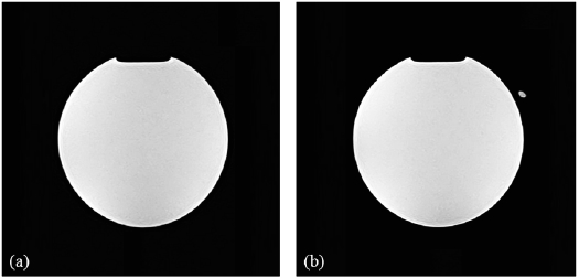
Figure 7 shows the SE T1-wighted images of the water phantom taken to measure the interference caused by the nasal-cavity attached fiber-optic respiration sensor. The distal sensor-tip of the respiration sensor is indicated by a marker in this figure. It can be seen that the sensing part of the nasal-cavity attached fiber-optic respiration sensor incorporating a thermochromic pigment-based temperature sensing film and a plastic optical fiber caused no deterioration of the MR image. Because artifacts due to the fiber-optic respiration sensor were not observed, it was verified that reliable MR image acquisition is possible.
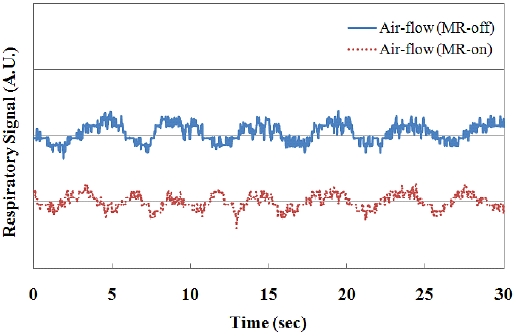
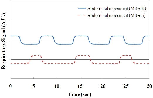
Figures 8 and 9 show the output voltage variations of the fiber-optic respiration sensors with the spontaneous breathing of the patient during the acquisition of MR images. The output voltages of the photodiode-amplifier system are changed by the temperature difference and variation of the abdominal circumference, respectively. In these real-time graphs, the respiratory signals are simultaneously measured during MR image acquisition, and the results show that the strong magnetic field did not affect the respiration signals.
Many kinds of respiratory sensors have developed using various kinds of techniques such as sensing of air-flow, humidity, temperature and abdominal circumference [1]. However, most sensors cannot be used in high electromagnetic fields due to induced interactive noises. In this study, we have developed the two types of MR-compatible fiber-optic respiration sensors such as nasal-cavity and abdomen attached types for non-invasive respiratory monitoring inside an MRI system. In the case of nasal-cavity attached type, even there is a fiber-optic temperature sensor using a thermochromic pigment, it has not been reported that a fiber-optic respiratory sensor is developed using a thermochromic film for measuring a temperature of air-flow in a nasal-cavity for MR-compatible uses. Also, there are many kinds of fiber-optic respiratory sensors which can measure thoracic or abdominal circumferences using a bending loss of optical fiber. However, we developed the abdomen attached fiber-optic respiration sensor using a reflectance method. Even this type sensor is very simple, it has high sensitivity and SNR according to movement of abdominal circumference and it can also be used in an MRI system.
In conclusion, we have fabricated MR-compatible fiberoptic respiration sensors and have measured modulated light, which is guided to a photodiode-amplifier system in the control room, via plastic optical fibers due to the airflow and abdominal movements, respectively. The respiratory signals of the fiber-optic respiration sensors were compared with those of the BIOPAC® system. In addition, we verified that respiratory signals can be obtained without deteriorating the MR image.
It is anticipated that the proposed fiber-optic respiration sensors would be highly suitable for respiratory monitoring during the performance of surgical procedures inside an MRI system. Further studies will be carried out to measure respiratory activity with other physiological signals such as temperature and PPG inside the MR room.