There have been many developments and studies of panoramic imaging systems not only in the traditional areas such as photographing buildings, nature scenes, and heavenly bodies, but also in security/surveillance systems using CCD (charge-coupled device) or CMOS (complementary metaloxide- semiconductor) cameras, in virtual touring of real estate, hotels and tourist resorts, and in navigational aids for mobile robots and unmanned aerial vehicles (UAV) [1-4].
One method of obtaining a panoramic image is to employ a fisheye lens with a wide field of view (FOV). For example, the entire sky and the horizon can be captured in a single image by pointing a camera equipped with a fisheye lens with 180℃ FOV toward the zenith. For this reason, fisheye lenses have often been referred to as “all-sky lenses”. In particular, a high-end fisheye lens by Nikon, namely, 6 mm f/5.6 Fisheye-Nikkor, has a FOV of 220℃. Therefore, a camera equipped with this lens can capture a portion of the view behind the camera as well as in front of the camera. Then, after proper image processing, a panoramic image can be obtained from the fisheye image.
In many cases, an imaging system is installed on vertical walls. Imaging systems installed on the outside walls of a building for the purpose of monitoring the surroundings, or a rear view camera for monitoring behind a passenger car are such examples. In such cases, it is inefficient if the horizontal field of view is significantly larger than 180℃. This is because a wall, which does not need to be monitored, takes up a large space in the monitor screen. Pixels are wasted in this case, and the screen is dull. Therefore, a horizontal FOV around 180℃ is more appropriate for such cases. Nevertheless, a fisheye lens with 180℃ FOV has undesirable features for such an application. This is because the barrel distortion which accompanies a fisheye lens evokes psychological discomfort and is disliked by the consumer.
An example of an imaging system which can be installed on an interior wall for the purpose of monitoring the entire room, is given by a pan/tilt/zoom camera. Such a camera is comprised of a video camera, which is equipped with an optical zoom lens, mounted on a pan/tilt stage. Pan is an operation of rotating in the horizontal direction for a given angle, and tilt is an operation of rotating in the vertical direction for a given angle. In other words, if we assume that the camera is at the center of a celestial sphere, then pan is an operation of changing the longitude, and tilt is an operation of changing the latitude. Therefore, the theoretical range of pan operation is 360℃, and the theoretical range of tilt operation is 180℃. The shortcomings of a pan/tilt/zoom camera include high price, large size and heavy weight. Optical zoom lenses are large, heavy and expensive due to the difficulty in designing and manufacturing. Also, a pan/tilt stage is an expensive device no cheaper than a camera. Therefore, it costs a considerable sum to install a pan/tilt/zoom camera. Furthermore, a pan/tilt/zoom camera is large and heavy, which can become a serious impediment to certain applications. Examples of such cases include airplanes where the weight of the payload is of critical importance, or where a strict size limitation exists in order to install a camera in a confined space. Furthermore, pan/ tilt/zoom operation takes time because it is a mechanical operation. Therefore, depending on the particular application at hand, such a mechanical operation may not be fast enough.
There has been much research about extracting panoramic or rectilinear images from fisheye images [5-9], even a patent describing an imaging system that is able to perform digital pan/tilt/zoom operations without a physically moving part. Ordinarily, when an imaging system such as a security camera is installed, a cautionary measure is taken so that a vertical line perpendicular to the horizontal plane also appears vertical in the acquired image. In such a case, vertical lines still appear vertical even as a mechanical pan/tilt/zoom operation is performed. On the other hand, in the above invention, vertical lines generally do not appear as vertical lines after the software pan/tilt/zoom operation has been performed. Furthermore, the above invention assumes that the projection scheme of the fisheye lens is an ideal equidistance projection scheme. But, the real projection scheme of a fisheye lens generally shows a considerable deviation from an ideal equidistance projection scheme. Since the above invention does not take into account the distortion characteristics of a real lens, images obtained after image processing still show distortion. The invention described in reference 9 remedies the shortcoming of the invention described in reference 8, namely the inability to take into account the real projection scheme of the fisheye lens used in image processing. Nevertheless, the defect of not showing vertical lines as vertical lines in the monitor screen has not been resolved.
The goal of this investigation is to provide methods of extracting mathematically precise and intuitively appealing digital pan/tilt/zoom images as well as polygonal panoramic images composed of multiple rectilinear images.
II. EXTRACTION OF RECTILINEAR IMAGE FROM A FISHEYE IMAGE
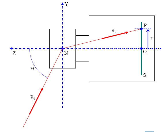
Figure 1 is a schematic diagram illustrating the projection scheme of a general wide-angle lens. The optical axis coincides with the Z-axis of the coordinate system, and the incidence angle θ of an incident ray Ri is measured as a zenith angle. All the rays forming image points on the image sensor plane S are considered to pass through the nodal point N of the lens. The intersection between the optical axis and the image sensor plane S is designated as origin O in Fig. 1. The refracted ray Rr corresponds to the incident ray Ri, and forms an image point P on the image sensor plane S. The radial distance from the origin O to the image point P is the image height r.
The general projection scheme of a lens can be defined as r = r(θ), where the image height r is a monotonically increasing function of the incidence angle θ. Such a real projection scheme of a lens can be experimentally measured using an actual lens, or can be calculated from the lens prescription using dedicated lens design software such as Code V or Zemax.
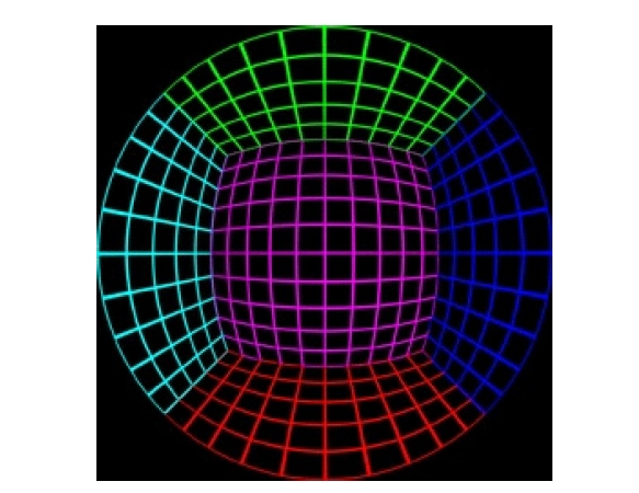
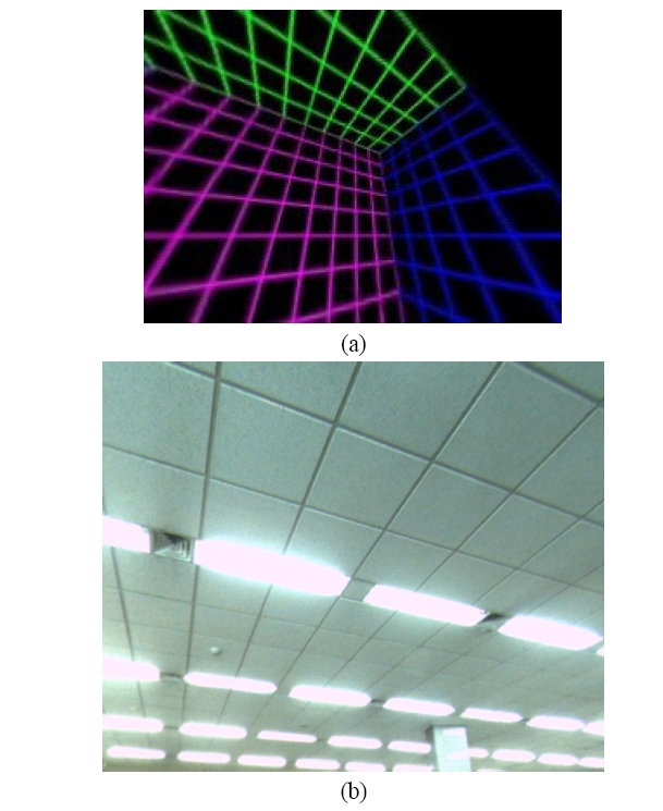
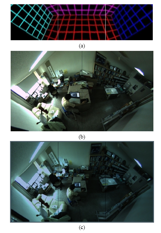
Figure 2 is an imaginary interior scene produced by Professor Paul Bourke by using a computer, and it has been assumed that the imaginary lens used to capture the scene is a fisheye lens with 180℃ FOV having an ideal equidistance projection scheme. This image is a square image, of which both the lateral and the longitudinal dimensions are 250 pixels. Therefore, the coordinate of the optical axis is (125.5, 125.5), and the image height for an incident ray
with a zenith angle of 90℃ is given as r'(π/2) = 125.5 - 1 = 124.5. Here, r' is not a physical distance, but an image height measured in pixel distance. Since this imaginary fisheye lens follows an equidistance projection scheme, the projection scheme of this lens is given by Eq. (1).
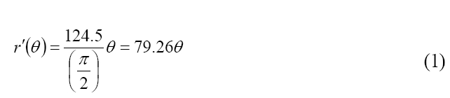
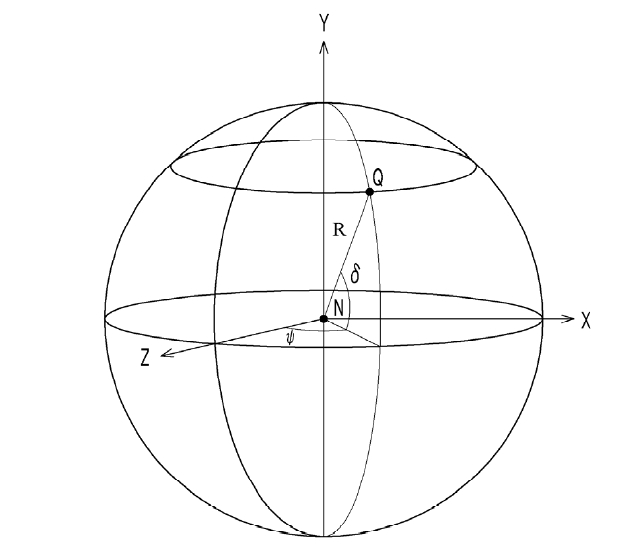
Figure 3 shows the world coordinate system employed in this section. The world coordinate system describes the object points in the outside world. The nodal point of the lens is taken as the origin of the world coordinate system, the vertical axis is taken as the Y-axis, and the optical axis is taken as the Z-axis. As has been illustrated in the figure, an object point Q is shown at a distance R from the origin N. An incident ray originating from this object point Q will have a horizontal incidence angle ψ and a vertical incidence angle δ in the world coordinate system.
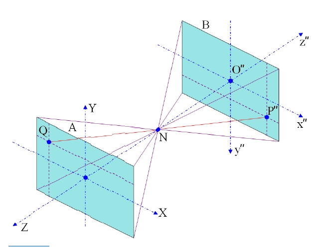
In this section, three other coordinate systems are further defined. Figure 4 is a schematic diagram illustrating the rectilinear projection scheme. By definition, a lens with a rectilinear projection scheme is a distortion-free lens, and from a mathematical viewpoint, the characteristics of a rectilinear lens are considered identical to those of a pinhole camera. To acquire an image with a rectilinear projection scheme, we assume an object plane A and a processed image plane B in the world coordinate system as shown in Fig. 4. The nodal point N is the common origin of all the coordinate systems. However, the world coordinate system is used to describe object points in the object plane A. Therefore, the X and Y-axis of the world coordinate system have been drawn near the object plane A.
The first rectangular coordinate system is a coordinate system for describing the image points on the image sensor
plane. The nodal point of the fisheye lens is taken as the origin of the first rectangular coordinate system, the optical axis is taken as the negative z-axis, the x-axis is parallel to the lateral side of the image sensor plane, and the y-axis is parallel to the vertical side of the image sensor plane.
The second rectangular coordinate system is a digitized version of the first rectangular coordinate system and used to describe the pixels in the uncorrected (i.e., distorted) image plane. The coordinate (x', y', z') of the second rectangular coordinate system is proportional to the coordinate (x, y, z) of the first rectangular coordinate system with a proportionality constant g. For example, if the lateral dimension of the image sensor plane is U and the longitudinal dimension is V, then the lateral dimension of the uncorrected image plane is gU and the longitudinal dimension is gV.
The uncorrected image plane can be considered as an image displayed on a monitor without rectification of distortion, and is a magnified image of the distorted real image on the image sensor plane by a magnification ratio g. For example, the image sensor plane of a 1/3-inch CCD sensor has a rectangular shape having a lateral dimension of 4.8 mm, and a longitudinal dimension of 3.6 mm, while the side dimension of a square pixel in a digital image is considered as 1. A VGA-grade 1/3-inch CCD sensor has pixels in an array form with 640 columns and 480 rows. Therefore, each pixel has a right rectangular shape with both width and height measuring 4.8 mm/640 = 7.5 ㎛, and in this case, the magnification ratio g is given by 1 pixel/ 7.5 ㎛ = 133.3 pixel/mm. In summary, the uncorrected image plane is a distorted digital image obtained by converting the real image formed on the image sensor plane into electrical signals.
The third rectangular coordinate system is a coordinate system for describing the pixels in the corrected (i.e., processed) image plane, and the third rectangular coordinate system takes the optical axis of the imaging system as the negative z"-axis, and the nodal point N of the lens as the origin. The image sensor plane has a rectangular shape
with a lateral width U and a longitudinal height V, and the image sensor plane is a plane perpendicular to the optical axis. The processed image plane has a rectangular shape with a lateral width W and a longitudinal height H. The x-axis of the first rectangular coordinate system, the x'-axis of the second rectangular coordinate system, the x"-axis of the third rectangular coordinate system and the X-axis of the world coordinate system are all parallel to the lateral side of the image sensor plane. Furthermore, the z-axis of the first rectangular coordinate system, the z'-axis of the second rectangular coordinate system, and the z"-axis of the third rectangular coordinate system are all identical to each other and opposite to the Z-axis of the world coordinate system. Similar to the X and Y-axis of the world coordinate system, the x" and y"-axis of the third rectangular coordinate system have been drawn near the processed image plane B.
The processed image plane B is assumed to be located at a distance s" from the nodal point N of the lens. In a rectilinear projection scheme, the shape of the object plane A is also a plane perpendicular to the optical axis, and the image of objects on the object plane is faithfully reproduced on the processed image plane with both the lateral and the longitudinal scales preserved. As has been stated, the ideal projection scheme of a rectilinear lens is identical to the projection scheme of a pinhole camera. Considering the simple geometrical characteristics of a pinhole camera, it is convenient to assume that the shape and the size of the object plane are identical to those of the processed image
plane. Therefore, the distance from the object plane A to the nodal point N of the lens is also assumed as s".
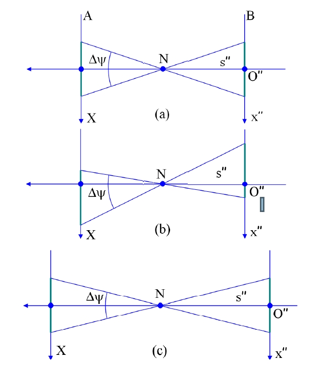
Figure 5 is a schematic diagram illustrating how the horizontal field of view Δψ of a lens is changed by the relative position of the processed image plane B. In Fig. 5(a), the position of the processed image plane is symmetric with respect to the opt'ical axis. Therefore, the image displayed on the processed image plane B has a symmetrical horizontal field of view. On the other hand, in Fig. 5(b), the processed image plane has been laterally displaced with respect to the optical axis, and the FOVs are different for the left and the right sides. Such an operation is useful when it is desired to change the monitored area without changing the principal direction of vision. Physically, it corresponds to laterally displacing the image sensor with respect to the optical axis. In this article, such an operation will be referred to as a slide operation.
Figure 5(c) shows the case where the distance s" between the nodal point N and the processed image plane B has been increased. In this case, as illustrated in the figure, the field of view becomes narrower, and only a small region is monitored. Physically, this corresponds to a zoom operation. Therefore, by changing the relative position of the processed image plane with respect to the optical axis, and the distance to the nodal point, slide and zoom effects can be achieved.
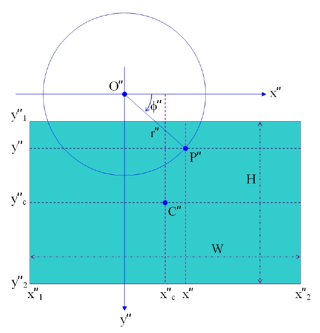
Figure 6 illustrates the case where the intersection O between the image sensor plane S and the optical axis, or equivalently the third intersection point O" on the processed image plane corresponding to the first intersection point O does not coincide with the center C" of the processed image plane. Therefore, it corresponds to an imaging system with slide operation. In a two dimensional rectangular coordinate system having the third intersection point O" as the
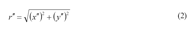
origin, the coordinate of the said center C" is given as (x"c, y"c). Since the lateral dimension of the processed image plane is W, the lateral coordinate with respect to the center C" has a minimum value x"1 = -W/2 and a maximum value x"2 = W/2. Considering the coordinate of the center C" on top of this, the range of the lateral coordinate of the processed image plane has a minimum value x"1 = x"c - W/2 and a maximum value x"2 = x"c + W/2. Likewise, the range of the longitudinal coordinate has a minimum value y"1 = y"c - H/2 and a maximum value y"2 = y"c + H/2. The distance between the third intersection point O" on the processed image plane to the third point P", or the image height r" is given by Eq. (2).
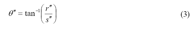
Since the virtual distance between the nodal point of the lens to the processed image plane is s", an incident ray arriving at the third point by the rectilinear lens has a zenith angle given by Eq. (3),
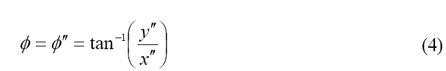
while the azimuth angle of the incident ray is given by Eq. (4).
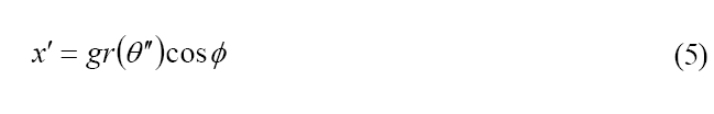
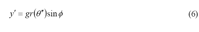
Therefore, when an incident ray having the above zenith angle and the azimuth angle forms an image point on the image sensor plane, the coordinate of the image point in the rectangular coordinate system is given by Eqs. (5-6).
Therefore, it is only necessary to substitute the signal value of the third point P" on the processed image plane having a rectangular coordinate (x", y") by the signal value of the image point P' on the uncorrected image plane having a rectangular coordinate (x', y').
In the absence of a slide action, in other words, when the position of the third intersection point coincides with the center of the processed image plane, the following equation given in Eq. (7) is satisfied.
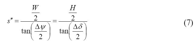
Using Eq. (7), the virtual distance s" of the processed image plane having a given horizontal or vertical FOV can be calculated. Purely for the purpose of convenience, the size (W, H) of the processed image plane and the horizontal FOV Δψ is first determined. Then, the virtual distance s" of the processed image plane is obtained, and from this distance, the symmetrical vertical FOV Δδ is automatically determined.
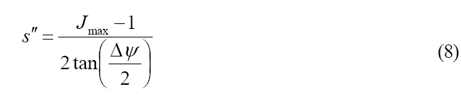
Considering the facts that all the image sensors and the display devices are digital devices, it is convenient to use the following equations in the image processing procedure. First of all, the size (Imax, Jmax) of the processed image plane and the horizontal FOV Δψ prior to any slide operation are determined. Then, the pixel distance s" between the nodal point of the lens and the processed image plane can be obtained using Eq. (8).
Finally, the coordinate of the center of the processed image plane is given by Eq. (9).
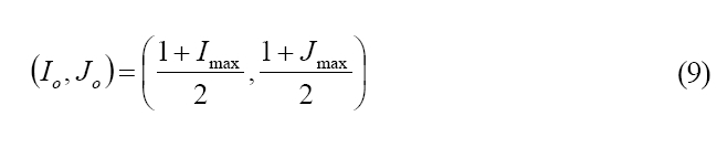
Here, Eq. (9) reflects the convention that the coordinate of the pixel on the upper left corner of a digital image is given as (1, 1).
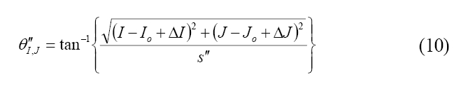
Next, according to the needs, the displacement (ΔI, ΔJ) of the center from the third intersection point is determined. Once such a preparatory stage has been finished, the zenith angle given in Eq. (10) and the azimuth angle given in Eq. (11) are calculated for every pixel on the processed image plane.
Next, the image height rI,J on the image sensor plane is calculated using Eq. (12).
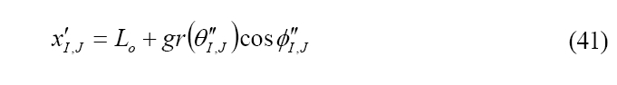
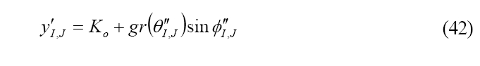
Next, the position of the second point on the uncorrected image plane is calculated using the position (Ko, Lo) of the second intersection point on the uncorrected image plane and the magnification ratio g.
Once the position of the corresponding second point has been found, the rectilinear image can be obtained using well-known interpolation methods.
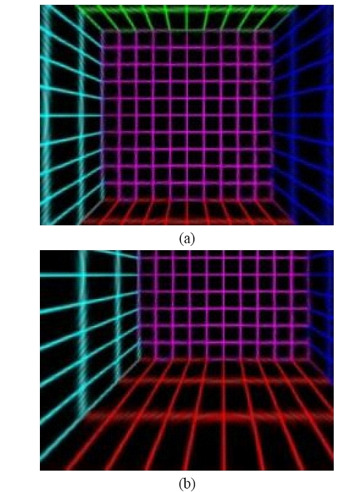
Figure 7(a) is a rectilinear image extracted from the fisheye image given in Fig. 2, where the lateral dimension of the processed image plane is 240 pixels, the longitudinal dimension is 180 pixels, the horizontal FOV is 120℃, and there is no slide operation. As can be seen from Fig. 7(a), all the straight lines are captured as straight lines. Figure 7(b) shows a rectilinear image, of which the parameters are identical to those of Fig. 7(a) except for the fact that the center of the processed image plane has been slid 70 pixels along the lateral direction and -30 pixels along the longitudinal direction.
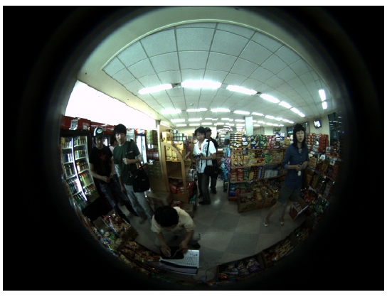
Figure 8 is an example of an image of an interior scene,
which has been acquired by aligning the optical axis of a fisheye lens with 190℃ FOV (described in reference 10) parallel to the ground plane. The real projection scheme of this fisheye lens is described in detail in said reference. Figure 9 is a rectilinear image extracted from Fig. 8 with the width: height ratio of 4:3, wherein the position of the third intersection point coincides with the center of the processed image plane, and the horizontal FOV is 60℃. Here, it can be seen that all the straight lines in the world coordinate system are captured as straight lines in the processed image plane.
IV. DIGITAL PAN/TILT/ZOOM/SLIDE OPERATION
If a camera equipped with a fisheye lens with 180℃ FOV is installed on an interior wall, then there is practically no dead zone of security monitoring because the region not captured by the camera is the wall, which need not be
monitored. However, as has been stated previously, an image by a fisheye lens causes psychological discomfort due to its barrel distortion. Although an ultra wide-angle image extracted in the manner of the previous section captures most of the interior scene, captured objects far from the optical axis do not appear natural to the naked eye. In this case, the most natural looking image is a rectilinear image that can be acquired by pointing the camera in the direction of the object.
A camera that can physically provide such an image is a camera equipped with a rectilinear lens and mounted on a pan/tilt stage. Since the camera can be oriented to the direction that needs the most attention, a most satisfactory image can be provided. Furthermore, images can be continuously produced while dynamically tracking a moving object such as a cat or an intruder. A method of realizing such functionality with software is provided as follows [11].
Due to the mathematical properties of three-dimensional rotations, different images are obtained depending on which of the two operations, namely a pan or a tilt operation, has been taken first. In this section, we assume that a pan operation has been taken first. Furthermore, as in the previous section, slide and zoom operations are allowed. The coordinate system describing the objects prior to the pan operation is the world coordinate system, and the X-Z plane coincides with the horizontal plane and the Y-axis coincides with the vertical axis. Furthermore, we assume that the optical axis coincides with the Z-axis prior to the pan operation.
The coordinate system after the pan operation is the first world coordinate system, and the coordinate system after the tilt operation is the second world coordinate system. The X", Y" and Z"-axes of the second world coordinate system are respectively parallel to the x, y and z-axes of the first rectangular coordinate system.
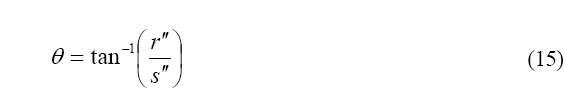
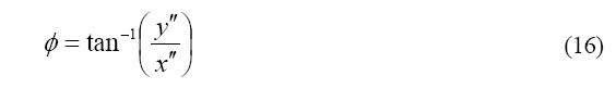
First of all, as in the previous section, the size (W, H) of the processed image plane and the horizontal FOV Δψ prior to the slide operation are determined. Then the distance s" of the processed image plane is determined by Eq. (7). Next, a proper amount (x"c, y"c) of slide operation is determined in order to obtain a desirable horizontal FOV (ψmin ≤ ψ ≤ ψmax) and a vertical FOV (δmin ≤ δ ≤ δmax). Every object point Q in the world coordinate system corresponding to the image point P on the processed image plane B has a zenith angle θ given by Eq. (15) and an azimuth angle given by Eq. (16).
Then, the coordinate of an object point Q at an object distance R from the nodal point of the lens is given by Eqs. (17-20).
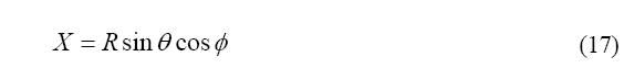
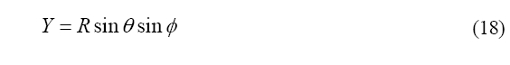
Here, the object distance R can take an arbitrary value, and can be taken as 1 for the sake of simplicity.
In the coordinate system of this section, pan operation is a rotational operation around the Y-axis, and tilt operation is a rotational operation around the X'-axis. The coordinate of a new point which corresponds to an object point in the world coordinate system having a coordinate (X, Y, Z) rotated around the Y-axis by angle -β is given as (X', Y', Z'), and the coordinate of yet another point which corresponds to the new point rotated around the X'-axis by angle -α is given as (X", Y", Z").
Regarding the rotation of coordinate system, it is convenient to use the Euler matrices. For this, the coordinate of an object point Q in three-dimensional space is designated as a three dimensional vector as given below.
Here, Q r is the three dimensional vector in the world coordinate system starting at the origin N and ending at the point Q. Then, the coordinate of a new point obtainable by rotating the point Q in the space by an angle of -α around the X-axis is given by multiplying the matrix given in Eq. (22) on the above vector.
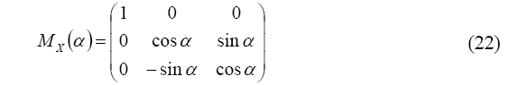
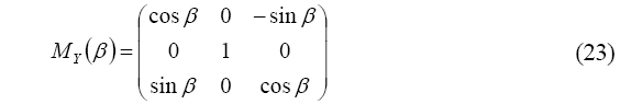
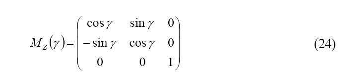
Likewise, the matrix given in Eq. (23) can be used to find the coordinate of a new point which is obtainable by rotating the point Q by angle -β around the Y-axis, and the matrix given in Eq. (24) can be used to find the coordinate of a new point which is obtainable by rotating the point Q by angle -γ around the Z-axis.
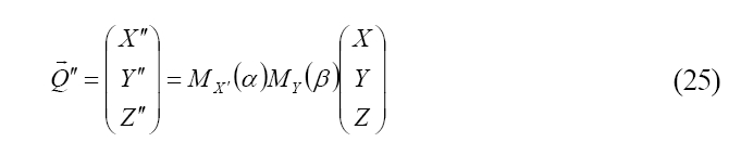
Matrices in Eqs. (22) through (24) can describe the case where the coordinate system is fixed and the point in space has been rotated, but also the same matrices can describe the case where the point in space is fixed and the coordinate system has been rotated in the reverse direction. These two cases are mathematically equivalent. Utilizing the Euler matrices, the coordinate of the new point is given by Eq. (25).
The following relation holds due to the mathematical properties of Euler matrices.
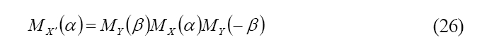
Therefore, Eq. (25) can be expressed in a simpler form as given below.
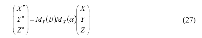
By calculating these rotational matrices, the coordinate of the new point is given by Eqs. (28-30).
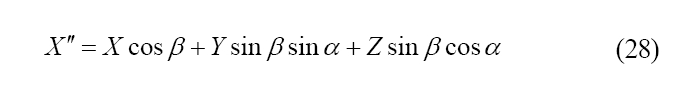
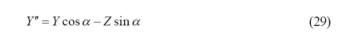
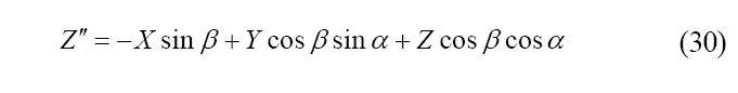
The procedure for finding the coordinate of the first point from the coordinate of this new point is identical to that of the previous section.
Considering the fact that all the image sensors and display means are digital devices, image processing for disital pan/tilt technology can be done using the procedure outlined below. First, the size (Imax, Jmax) of the processed image plane, the horizontal field of view Δψ, the vertical field of view Δδ, and the pixel distance s" from the nodal point of the lens to the processed image plane are obtained. Next, the coordinate of the object point Q in the world coordinate system is calculated using Eqs. (31) through (35).
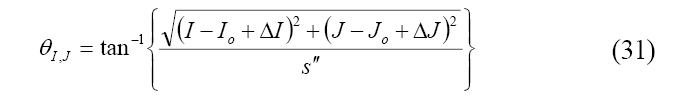
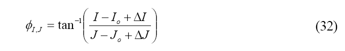
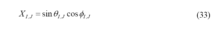
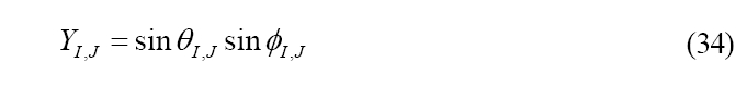
Here, the object distance R has been assumed as 1. Next, the coordinate of this object point in the second world coordinate system is calculated using Eqs. (36-38).

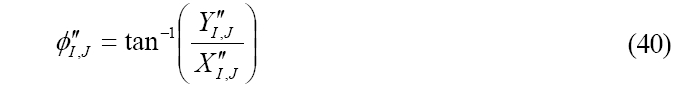
From this coordinate, the zenith angle θ"I,J and the azimuth angle ?"I,J of the incident ray are calculated using Eqs. (39-40).
Next, the position of the second point on the uncorrected image plane is obtained from the position (Ko, Lo) of the second intersection point on the uncorrected image plane and the magnification ratio g.
Once the position of the second point has been found, the rectilinear image can be obtained using interpolation methods.
Figure 10(a) is a rectilinear image extracted from the fisheye image given in Fig. 2, wherein the lateral dimension of the processed image plane is 240 pixels, the longitudinal dimension is 180 pixels, the horizontal FOV prior to the pan/tilt operations is 120℃, there is no slide
operation, and the rotation angles are given as α = β = 30℃. operation to the fisheye image given in Fig. 11. As can be seen from Fig. 10(a), all the straight lines are captured as straight lines. Fig. 10(b) is a rectilinear image extracted from the fisheye image given in Fig. 8, wherein the lateral dimension of the processed image plane is 1280 pixels, the longitudinal dimension is 960 pixels, the horizontal FOV prior to the pan/tilt operations is 70℃, there is no slide operation, and the rotation angles are given as α = 40℃ and β = 20℃.
V. DIGITAL TILT/PAN/ZOOM/SLIDE OPERATION
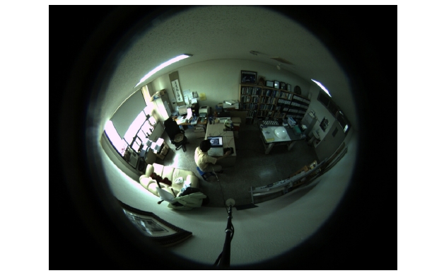
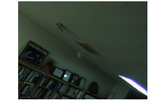
Figure 11 is another example of an image of an interior scene captured using a fisheye lens described in reference 10, wherein the optical axis of the fisheye lens has been inclined downward from the horizontal plane toward the floor (i.e., nadir) by 45℃, while Fig. 12 is a rectilinear image extracted from Fig. 11 with pan/tilt operations. Specifically, the lateral dimension of the processed image plane is 1280 pixels, the longitudinal dimension is 960 pixels, the horizontal FOV prior to the pan/tilt operations is 60℃, there is no slide operation, and the rotation angles are given as α = 45℃ and β = 50℃. From the figure, however,
it can be seen that vertically extended objects such as the bookshelves appear slanted. In such a case, a satisfactory image can be obtained when the tilt operation precedes the pan operation.
In other words, the method of extracting a rectilinear image presented in the previous section is a method wherein the pan and the tilt operations follow in sequence. However, depending on the application area, it can be more advantageous if the order of the pan and the tilt operations are exchanged. In this case, the coordinate of a new point obtainable by taking the tilt and the pan operations in sequence is given by Eq. (43).
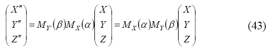
By evaluating these rotational matrices, the coordinate of the object point in the second world coordinate system is given by Eqs. (44-46).
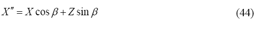
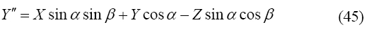
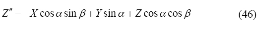
The procedure for finding the coordinate of the second point from the coordinate of the object point is identical to that given in the previous section.
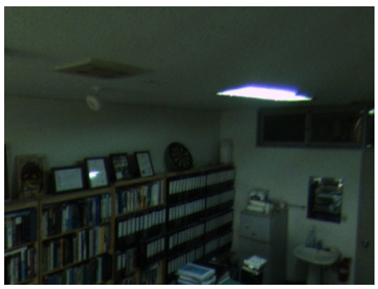
Figure 13 is a rectilinear image extracted from the fisheye image given in Fig. 11 with tilt and pan operations. It can be seen from the figure that the bookshelves appear to stand in an upright position.
VI. POLYGONAL PANORAMIC IMAGE COMPOSED OF MULTIPLE RECTILINEAR IMAGES
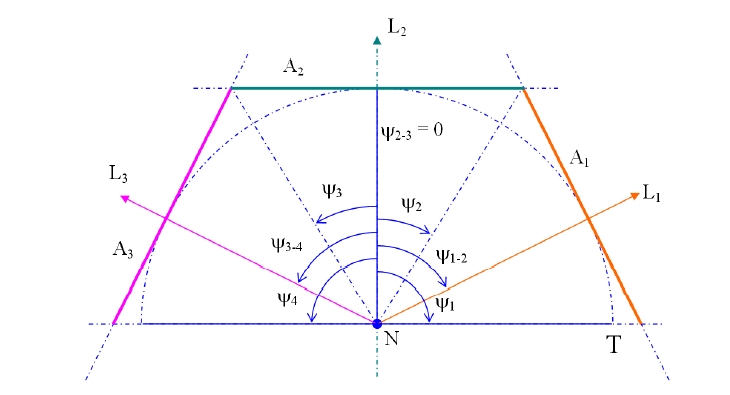
Figure 14 is a schematic diagram of an object plane providing a polygonal panoramic image that can be advantageously used for moving vehicles such as automobiles, autobikes and airplanes [11]. This can be considered as a generalized version of a cubic panorama [12].
For such a polygonal panoramic image, the object plane has a structure with more than two sub-object planes joined together, where each of the sub-object planes is a planar surface by itself. Although Fig. 14 is illustrated as a case where three sub-object planes, namely A1, A2 and A3 are used, a more general case of using n sub-object planes can be easily understood as well. In order to easily understand such case, a sphere with a radius T centered on the nodal point N of the lens is assumed. If a folding screen is set-up around the sphere while keeping the folding screen to touch the sphere, then this folding screen corresponds
to the object plane. Therefore, the n sub-object planes are all at the same distance T from the nodal point of the lens. As a consequence, all the sub-object planes have the identical zoom ratio or the magnification ratio.
In Fig. 14 using three sub-object planes (A1, A2, A3), the principal direction of vision L1 of the 1st sub-object plane A1 makes an angle of ψ1-2 with the principal direction of vision L2 of the 2nd sub-object plane A2, and the principal direction of vision L3 of the 3rd sub-object plane A3 makes an angle of ψ3-4 with the principal direction of vision L2 of the 2nd sub-object plane A2. The range of the horizontal FOV of the 1st sub-object plane A1 is from a minimum value ψ1 to a maximum value ψ2, and the range of the horizontal FOV of the 2nd sub-object plane A2 is from a minimum value ψ2 to a maximum value ψ3. By having the horizontal FOVs of adjacent sub-object planes seamlessly continued, a natural-looking polygonal panoramic image can be obtained.
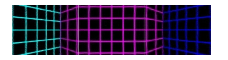
Figure 15 is an example of a polygonal panoramic image extracted from Fig. 2, wherein each sub-processed image plane is 240 pixels wide along the lateral direction and 180 pixels high along the longitudinal direction. Furthermore, the horizontal FOV of each of the sub-object planes or the sub-processed image plane is 60℃, there is no slide operation for each sub-object plane, and the distance to the sub-object plane is identical for all of the sub-object planes. The pan angle for the 3rd sub-object plane on the left side is -60℃, the pan angle for the 2nd sub-object plane in the middle is 0℃, and the pan angle for the 1st sub-object plane on the right side is 60℃. Since, each of the three sub-object planes has a horizontal FOV of 60℃, the three sub-object planes comprise a polygonal panoramic image having a horizontal FOV of 180℃ as a whole. As can be seen from Fig. 15, all the straight lines appear as straight lines in each sub-object plane.
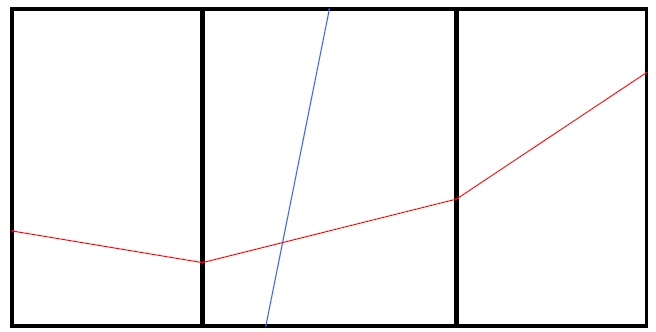
Figure 16 is a schematic diagram illustrating the definition of a polygonal panoramic image. An imaging system providing a polygonal panoramic image includes a camera for acquiring an uncorrected image plane that is equipped with a fisheye lens, an image processing devices for extracting a polygonal panoramic image from the uncorrected image, and a screen for displaying the polygonal panoramic image. A polygonal panoramic image is comprised of the 1st through the nth sub-rectilinear image planes laid out horizontally on the screen, where n is a natural number larger than 2, an arbitrary straight line in the world coordinate system appears as a straight line on any of the 1st through the nth sub-rectilinear image planes, and any straight line in the world coordinate system appearing on more than two adjacent sub-rectilinear image planes appears as a connected line segment.
Figure 17(a) is another polygonal panoramic image extracted from Fig. 2. This is a polygonal panoramic image obtained by first tilting the three sub-object planes by -55℃, and then subsequently panning the sub-object planes by the same condition applied to Fig. 15. As can be seen from Fig. 17(a), even if the vertical lines in the world coordinate system are not parallel to the longitudinal side of the image sensor plane, they still appear as straight lines in the processed image plane. Figures 17(b-c) are polygonal panoramic images extracted from Fig. 11. In Fig. 17(b), each of the two object planes has a horizontal FOV of 190℃/2, and in Fig. 17(c), each of the three object planes has a horizontal FOV of 190℃/3.
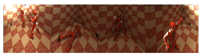
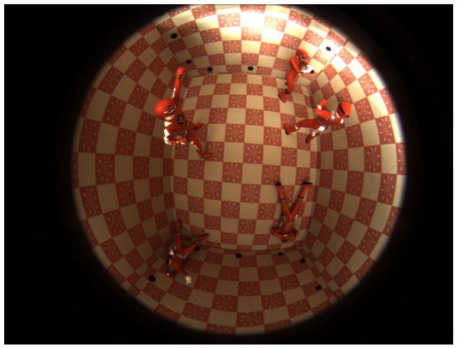
Figure 18 is another example of a fisheye image, and it shows the effect of installing a fisheye lens with 190℃ FOV on the center of the ceiling of an interior. The image has been obtained by placing figurines from a comic movie inside a reinforced fabric packing box. The camera with the fisheye lens has been hung over the packing box. Figure 19 is a polygonal panoramic image extracted from Fig. 18. Each sub-object plane has a horizontal FOV of 360℃/4, and it has been obtained by tilting all the sub-object planes by
-90℃ first, and subsequently panning the sub-object planes
[Fig 19] An example of a polygonal panoramic image extractedfrom the fisheye image given in Fig. 18.

by necessary amounts. From Fig. 19, it can be seen that such an imaging system will be useful as an indoor security camera.
In conclusion, we have developed mathematically precise image-processing algorithms for extracting rectilinear images from fisheye images as well as digital pan/tilt/zoom/slide technology. Using this technology, vertical lines always appear as vertical lines in the panned and/or tilted images. Furthermore, polygonal panoramic images composed of multiple rectilinear images have been obtained using the developed digital pan/tilt technology.