Recently, broad frequency bandwidth has become in demand as data traffic has increased owing to a large number of multimedia data transmissions. However, as the available frequency bandwidth is limited, the securing of a new bandwidth or the identification of new ways of using existing bandwidth efficiently is needed. When sharing TV White Space (TVWS), in the case of the latter, spectrum sensing should be done to determine the unoccupied frequency bandwidth, avoiding primary users. The research regarding this problem has been actively ongoing and many methods of spectrum sensing were proposed [1]. In order to acquire a high tuning speed as well as the accuracy, we propose a narrowband tunable bandpass filter, which is used to scan TVWS at a higher speed.
Up to now, diverse tunable filters have been proposed [2–10]. However, most designs suffer from narrow tuning ranges, unequal tuning bandwidths, or high insertion loss for narrow passband bandwidth. Hence, the tunable bandpass filters (BPF) design methods are not suitable for use in the TVWS band (470–698 MHz). Therefore, in this paper, we propose an efficient method, which covers a wide frequency range with narrow tuning bandwidths.
The tunable filter suggested in this paper switches 11 LC tank circuits through PIN diode to cover the whole TVWS band. In addition, while maintaining a constant bandwidth from 480 MHz to 680 MHz, it can be tuned at intervals of 20 MHz. With one varactor diode added, minute frequency tuning becomes possible. For efficient spectrum sensing, we have to design a BPF with a narrow bandwidth in order to reduce the noise floor. In such case the large insertion loss is inevitable due to the low Q resonant section. By adding the active capacitance circuit designed in broadband [11], we can effectively reduce the insertion loss.
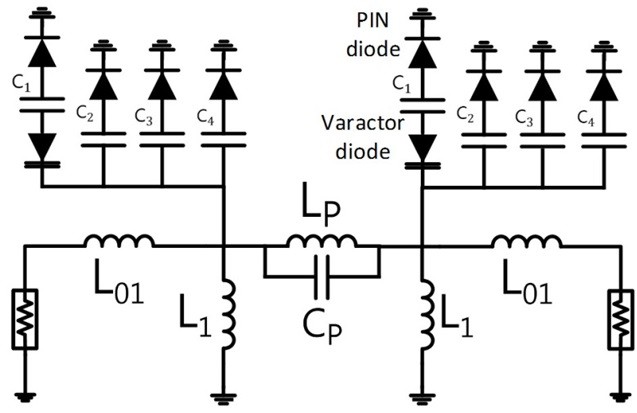
The tunable BPF proposed in this paper is derived from Chebyshev filter response, which is composed of lumped element resonators and an L-coupled structure is used [12] as shown in Fig. 1.
1. Tuning Method (Composition of Resonator)
The proposed filter uses the PIN diodes and a varactor diode to vary the capacitive loading on the LC resonant section of Fig. 1 to change the center frequency of the filter. The voltages applied to the PIN diodes which are operating as on/off switches connected to capacitors, allow the resonator to have an appropriate capacitance. The parasitic capacitance introduced by PIN diodes are added to the existing capacitor bank which results in the lowering the center frequency of the filter. For a minute frequency tuning a varactor diode is employed. In this way, one can tune each of the 11 channels at 20-MHz spacing in the 480–680 MHz band.
2. Design of the Constant Bandwidth Filter
When we design a BPF using lumped elements, the values of
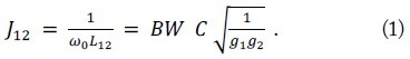
And the filter bandwidth can be expressed as

where
where


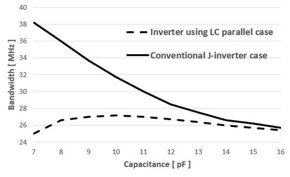
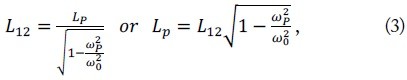
Since the above two bandwidths are supposed to be the same, one can obtain the constant bandwidth condition as
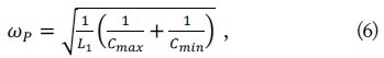

Thus when the inverter that connects the resonators is replaced by an LC parallel circuit as in Fig. 1, it is possible to maintain a constant bandwidth. In Fig. 2 we plotted the constant bandwidth condition together with the conventional L-coupled case, both of which were simulated through MATLAB.
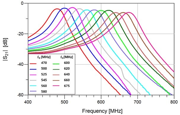
Fig. 3 shows the measured frequency characteristics of the designed tunable BPF which the center frequency
III. DESIGN OF ACTIVE TUNABLE BPF
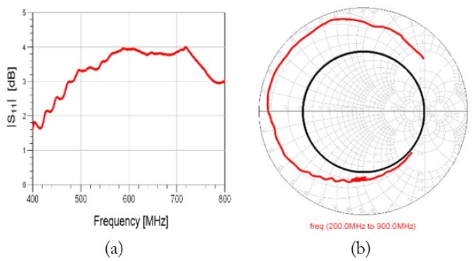
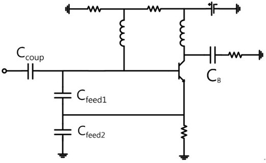
Since the quality factor of the resonant circuit is low, the proposed tunable BPF suffers a relatively high insertion loss. Therefore, we added an active capacitance circuit that compensates for the insertion loss. We modified the active capacitance circuit given in [11] in order to acquire the negative resistance within the wide TVWS band. Since the insertion loss becomes larger as the frequency goes higher, the value of the negative resistance must also be larger as the frequency goes higher, as shown in Fig. 4. In Fig. 5 the capacitor
Therefore, we chose the magnitude of the negative resistance in such a way that the accompanied capacitor does not affect the resonant frequencies very much [11].
IV. SIMULATED AND MEASURED RESULTS
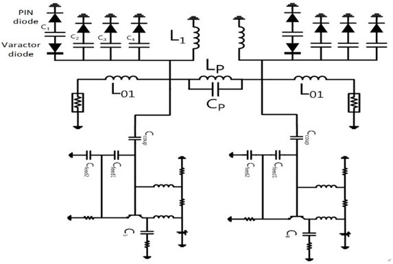
By combining the active capacitance circuit and the resonator of the tunable BPF, we can design the active tunable BPF, as shown in Fig. 6. In this process, about 0.1 pF from the active capacitance circuit element from the active circuit is added to the resonator so that the resonant frequency of the filter is shifted 4.8 MHz. In this paper, a varactor diode was also used to compensate for this frequency shifts. Also, the capacitance from the PIN diode and substrate cannot be ignored so that we should be considered before synthesizing. We measured the parasitic capacitance of the PIN diode and the substrate and included it to the capacitor bank.
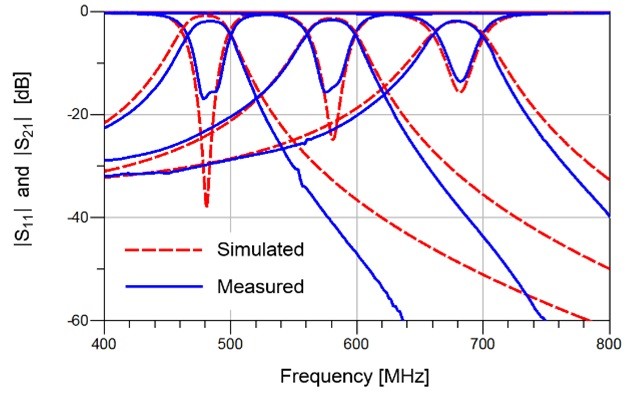
A comparison of the simulated and the measured results for 3 selected channels is shown in Fig. 7. The simulation results are obtained by Keysight Technologies’ Advanced Design System (ADS) 2014.
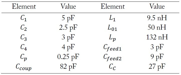
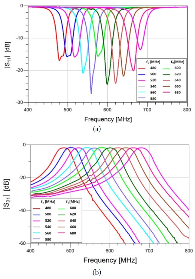
In the proposed active tunable BPF, we use the BFP620 BJT of Infineon Corporation in order to obtain the negative resistance, and the design values of the lumped elements are presented in Table 1. The filter was fabricated on the FR-4 substrate with a thickness of 1.6 mm, a dielectric constant of 4.3, and a tangent loss of 0.022. Fig. 3 shows the frequency responses of the designed tunable BPF without the compensation of the loss by the active circuit. In this case the maximum insertion loss within the whole tuning range reaches 6.07 dB. Contrary, Fig. 8(a) and (b) show the filter performances which is compensated by the active circuit. By adding the active capacitance circuit, the insertion loss has been measured less than 2.0 dB within the whole tuning range. The 1-dB bandwidth for each tuning frequency is a 25-MHz bandwidth within a tolerance of approximately 5%. The measured characteristics of BPF with active capacitance compensation show that the tenability remains almost the same as the one given in Fig. 3. The PIN diode used in this design is M/A-COM’s MA4P504-1072T, and the bias voltage for the PIN diode is applied to a 1.1 V. The varactor diode is Toshiba’s 1SV270. By adding the active capacitance circuit, much more efficient and accurate spectrum sensing is available. The measured OIP3 at each tuning frequency of the TVWS band has values of 19.33–20.83 dB. Compared to the typical OIP3 of BFP620 used to constitute the active capacitance circuit, it can be seen as a reasonable value.
[Table 1.] Element values of the designed circuit

Element values of the designed circuit
The center frequency of the tunable bandpass filter is controlled by MATLAB and the value of the required capacitor value for each tuning channel is constituted by a lookup table.
In this paper, we present an active tunable BPF that has a constant bandwidth and 11 channels to cover the TVWS (470–690 MHz) band for the efficient spectrum sensing application. The designed tunable BPF employs the lumped elements, and the frequency tuning is done by switching the capacitance in the capacitor bank comprised of PIN diodes and a varactor diode. In order to reduce the insertion loss, the active capacitance circuit was coupled to the tunable BPF. Simulated and measured results confirmed the performances of the tunable BPF having a small insertion loss of less than 2 dB in the wide TVWS band.