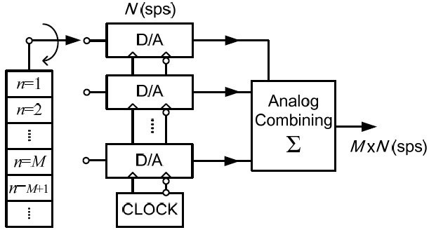
To realize the deployment of 5G systems, methods to calibrate signal generators with wide bandwidths are being studied [1,2]. The high-speed signals required for 5G systems are generally synthesized by incorporating medium-speed digital-toanalog converters (DACs) as if the overall speed reaches multiple times the speed of an individual DAC [3]. Many methods are available for increasing the sampling speed. One such method is called time interleaving (TI), in which the output of each DAC in the time domain is combined. It is used in many converting devices such as analog-to-digital converters (ADCs) and DACs [4,5]. These systems require a high-speed clock to drive the output switch in such a way that the output current of the low-speed DAC is directed alternatingly toward the output port; as a result, the final combined current is equivalently composed in accordance with the high-speed sampling clock.
However, in practice, TI devices cause additional errors owing to the non-idealities of the additional process. For example, in TI DACs and ADCs, clock jitter causes random phase errors in the equivalent sampling pulse train, resulting in irregular spurs in the frequency domain [6]. In addition, because high sampling speed in digital converters is often achieved at the expense of the bit resolution, the quantization error cannot be ignored as a random noise source, especially when digital converters with speeds exceeding hundreds of mega samples per second are concerned [7]. On the other hand, systematic errors such as the non-uniform analog characteristic between the lowspeed DACs also degrade the signal quality. Finally, because the calibration process is based on discrete Fourier transform (DFT), it is critical to maintain synchronization between the measurement equipment and to carefully design the reference waveform; otherwise, unintended artifacts are introduced from the windowing and picket-fence effects [8].
The author has proposed correction methods for a TI DAC system [2, 9]. However, it showed somewhat limited performance, presumably owing to the residual random noise and lack of accurate de-embedding. In this paper, we addressed these issues by using a novel noise model and Kalman filtering for correcting the statistical error. Furthermore, a co-simulation platform was implemented to enable systematic non-ideality correction across the time, frequency, and constellation domains.
II. COMBINING OUTPUT WAVEFORMS
Various methods can be used to combine the output of each converter. Among these, the TI technique is widely used because it affords high combining ratio [4–7]. Whereas TI ADCs incorporate tens of ADCs, commercial TI DACs mostly use a combination of only two DACs [4].
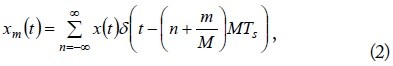
In the TI architecture, the band-limited output waveform
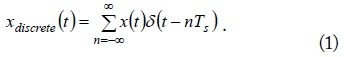
This is the result of TI combination, from which the

where
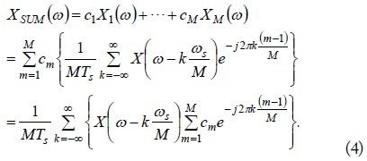
As a result, its Fourier transform is
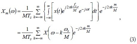
where
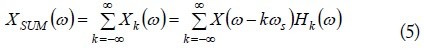
Therefore, the TI output

In addition,
where
Therefore, the non-uniform path coefficients
Furthermore,
III. CORRECTION BY KALMAN FILTERING
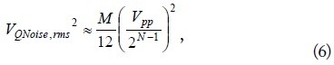
The finite resolution of DACs causes quantization noise at the output. The

where
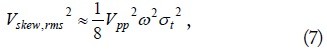
Furthermore, jitter in the sampling clock causes noise power, which is estimated as follows [5]:

where is the variance of the timing jitter.
Square-summing these noise voltages gives the total random noise voltage as
Because this noise is random and white over the entire sampling frequency, a Kalman filter is applied to reduce the noise power.
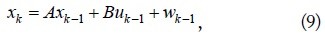
A Kalman filter is effective for estimating the state of a discrete-time controlled process

and the measurement equation
where the process noise covariance
The process noise
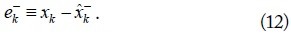
When the a priori state estimation error at step

The a posteriori error
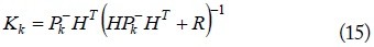
The error covariance matrix is defined from
It is then used to update the Kalman gain of state

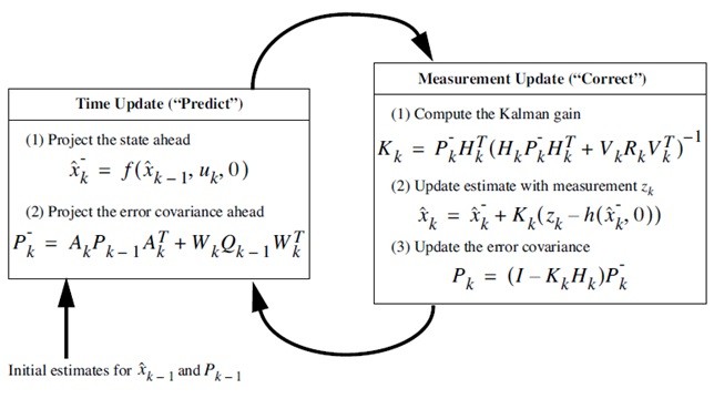
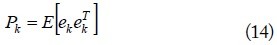
Fig. 2 shows the complete Kalman filter update operation. For applying the Kalman filter to the TI DAC system, the state vector
IV. MEASUREMENT AND CO-SIMULATION
The path coefficients in Section II are identified by carefully designed waveforms that occupy the frequency band of interest. In this regard, a high-speed 64 quadrature-amplitude-modulated (QAM) waveform was synthesized at 2 GHz with speed of 4.8 Gbps and signal-to-noise-ratio exceeding 43 dB. For identifying the path coefficients, a commercial arbitrary signal generator (AWG) with two 8-bit TI DACs was measured using the QAM waveform and a digitizer.
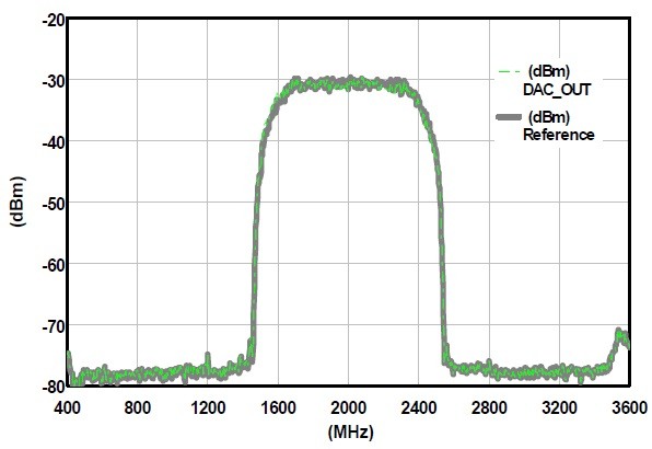
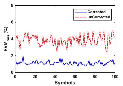
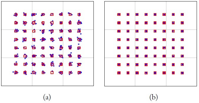
Furthermore, to estimate the signal quality degradation from the random noise and systematic non-ideality, a TI DAC system with the same configuration was modeled and implemented on a simulation platform. The simulator calculates the errorvector-magnitude (EVM) as a metric of the signal quality. Fig. 3 shows the implemented system with the QAM reference source and the RF up-converter to 2 GHz. By applying the Kalman filter to the measured waveforms, an accurate set of path coefficients was obtained, and it was loaded on the simulation platform to represent the system non-ideality. The Kalman gain was tuned to converge within five measurements. The filter coefficient was used to correct the system non-idealities throughout TI paths. Fig. 4 shows the spectrum of the reference QAM signal and the uncorrected DAC output. The identified path response of the AWG has in-band ripple of ±2 dB and roll-off from the sampling aperture. The path response was stored in a file and loaded into the simulation platform for the co-simulation to represent the system artifact in the TI DAC system. As a result, the received signal shows degraded quality, as in Fig. 5(a), in which the detected QAM constellation is overlaid on the reference symbol locations. Because the overall system is assumed to be quasilinear, the systematic error is corrected by the inverse coefficient, which consists of a wideband correction filter. As such, the correction filter is calculated and applied in the co-simulation platform. Figs. 5(b) and 6 show the result of the correction. As shown in these figures, the suggested correction clearly improved the EVM from 4.1% to 1.13%; this is consistent with the SNR improvement of 4.5 dB as obtained by a commercial vector signal analyzing software. The overall mean error in the EVM over 100 symbols was approximately 1.124% ± 0.22%. For the sake of comparison, correction was performed without the Kalman filter, and it showed EVM of about 1.43%.
This paper presented systematic and stochastic methods for the correction of multi-gigabit-per-second signals with AWGs that include TI DACs. BY using Kalman filtering, accurate system coefficients between each DAC are identified, and then, correction filter coefficients to overcome non-uniform path responses are calculated. Through a co-simulation of the AWG system, we improved the EVM from 4.1% to 1.13% for a 4.8 Gsps, 64-QAM modulated signal with 2-GHz carrier frequency. As an extension of this study, this approach could be useful to calibrate multiple TI converting systems to compensate for both systematic and stochastic error sources.


![Operation of Kalman filter [10].](http://oak.go.kr/repository/journal/21348/E1ELAT_2017_v17n1_39_f002.jpg)