Circularly polarized (CP) antennas have been widely used in many applications such as global positioning systems, satellite communication, RADAR, radio astronomy, and RFID systems. Circular polarization affords two main advantages in such applications: it avoids polarization misalignment as the electric field (E-field) rotates, and it reduces multipath fading because as long as the incident wave angle is less than the Brewster angle, the reflected CP wave has reversed rotation direction, resulting in cross-polarization (XPOL) [1–3].
CP radiation can be obtained under the condition that two orthogonal modes are generated with equal amplitude and 90° phase difference. For example, two typical methods, the one- and two-point feeding methods, are well known to circularly polarize patch antennas. In addition, the normal and axial modes of helix antennas are well known [4,5]. The spiral antenna technique is well known as a broadband CP antenna using a travelling wave [6–8]; however, the dispersive characteristics must be considered when a pulse signal is required for RADAR and UWB systems [9]. Signal processing can be used to avoid the effect of the characteristics. However, such processing is not suitable for high-speed communications. Therefore, wideband CP antennas with nondispersive characteristics are required.
For this purpose, broadband CP antennas require broadband impedance and axial ratio (AR) characteristics as well as constant gain and group delay characteristics. In addition, it is important to avoid multipaths. Furthermore, low XPOL resulting in low AR is needed over a wide range of angles in the radiation pattern.
Recently, several techniques for obtaining CP radiation in a wideband have been studied. Some give low Q value to obtain wideband 3-dB AR bandwidth and impedance [10–12]. A study showed that a metasurface structure called an artificial ground structure (AGS) that consists of a periodic structure on a planar substrate can work as an artificial magnetic conductor [13] and a polarizer [14]. The AGS can extend the AR bandwidth of CP patch antennas [15, 16].
High-gain antennas with broadband AR have also attracted research interest. The author has proposed some broadband CP waveguide antennas using an L-shaped probe [17, 18]. By using the fundamental mode, 3-dB AR bandwidth of around 24% can be achieved easily. This AR bandwidth can be extended by suppressing higher-order modes. Some broadband waveguide CP antennas using an L-shaped probe have been presented in [19–21]. Compared to these planar slot structures, waveguide antennas can achieve broadband performance and high gain and easily yield circular polarization covering a wide azimuth range in the radiation pattern. The author has discussed how such antennas can achieve the required performance mentioned above [22–25].
Ⅱ. REDUCTION OF HIGHER-ORDER MODES
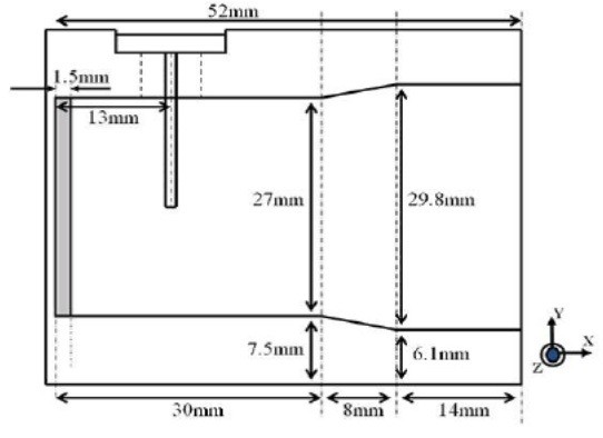
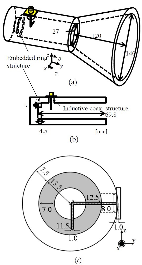
An L-shaped probe used to feed the waveguide antenna causes circular polarization with wideband characteristics. Fig. 1 shows an example of a waveguide antenna with a horn and an L-shaped feeding probe. In this structure, the horn antenna was designed using conventional formulas for obtaining an antenna gain of 17 dBi. In addition, an L-shaped probe was installed to generating circular polarization.
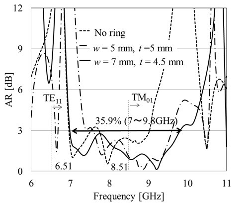
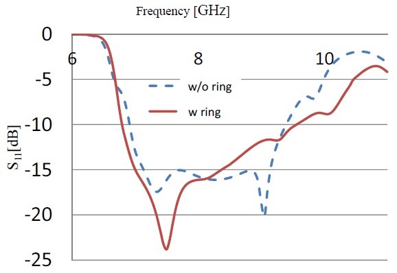
In Fig. 1, a metallic ring is embedded deep inside the waveguide. Fig. 2 shows the AR characteristics in the antenna boresight. If this metallic ring is removed, the 3-dB AR bandwidth in the boresight will be about 25% [17, 18]. In the frequency between around the cutoff frequency of TE11 (6.51 GHz) and the first higher-order mode (HOM) of TM01 (8.51 GHz) modes, the AR exceeds 3 dB. The proposed antenna has an asymmetrical structure in the cross section; therefore, the HOM can easily exist in the waveguide, and the field distribution depends on the frequency. Therefore, in the frequency region of the HOM, maintaining low AR is difficult. For wideband CP antennas, it is important to reduce HOM. For example, in the case of CP antennas, having a symmetrical structure such as 4-point feeding can reduce the HOM of TM21 modes even though TE11 is the fundamental mode.
Therefore, for expanding the wideband AR characteristics, the HOM should be removed. For this purpose, we use the embedded metallic ring. By choosing the dimensions of
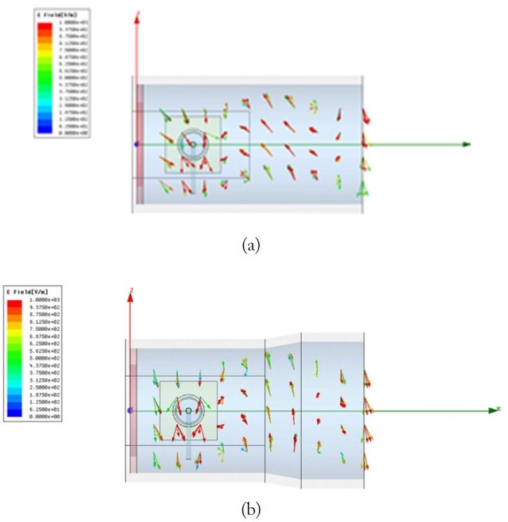
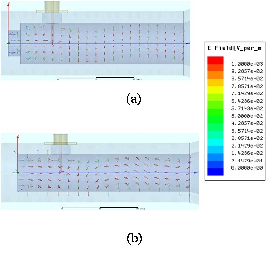
To confirm this behavior, we examine the distribution of the E-field at 9 GHz (HOM band) as shown in Fig. 3. In the waveguide with no ring, shown in Fig. 3(a), the E-field in some parts has components parallel to the propagation direction. This indicates that the field includes the TM01 mode considering the frequency. On the other hand, when the metallic ring is installed as shown in Fig. 3(b), the E-field in all parts has no component parallel to the propagation direction. We understand that only the TE mode can exist in the waveguide, which contributes to generate CP. CP from the L-shaped probe is generated on the principle that the phase of the current on the probe side along x lags by 90° compared to that along
Ⅲ. ENHANCEMENT OF AR BANDWIDTH AND ANGLE OF CP RADIATION
This section discusses some techniques to enhance the AR and angle of CP radiation in radiation patterns. For this purposes, HOM should be reduced. This is an important problem in broadband antennas with an asymmetrical structure, like this structure including the L-shaped probe, because the field of the HOM depends on the frequency. When designing a broadband antenna, it is important to keep a certain field with respect to the frequency. On the other hand, the field of HOM depends on frequency, resulting in limiting the constant characteristics in terms of frequency.
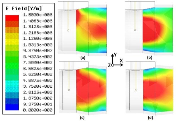
Fig. 6 shows a broadband waveguide antenna structure using the L-shaped probe, where we have installed a step in the aperture. Fig. 7 shows the effect of the aperture step. Fig. 7(a) shows an E-field distribution at 10 GHz in the structure in which the aperture step is removed. In this figure, we see that some E-field vectors have a component parallel to the propagation direction. This indicates that the HOM of the TM mode is included. On the other hand, Fig. 7(b) shows that installing an aperture step in around a location where the TM mode seems strong can control the E-field distribution and make all E-fields directed normal to the wall. This indicates that the HOM of the TM mode has vanished.
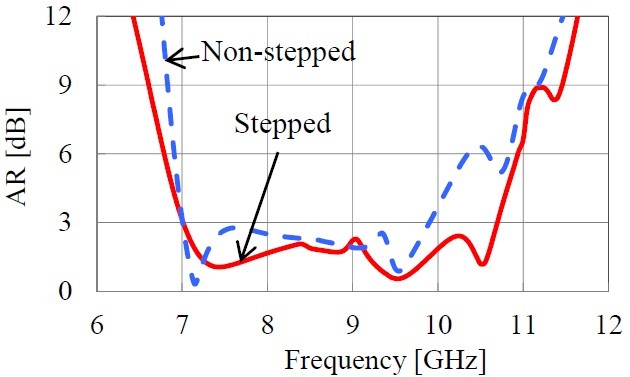
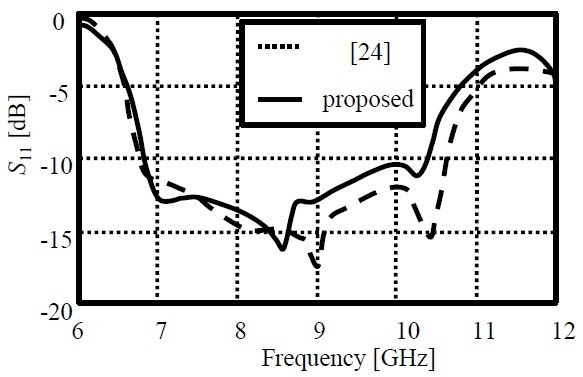
Choosing the location of the aperture step is important for this improvement. For building this stepped structure, we choose a location where the TM mode seems strong. If we simply install the step near the aperture, a similar effect will not be produced. In fact, the effect of the aperture step can be seen in the AR characteristics. Fig. 8 shows the AR characteristics for structures with both stepped and non-stepped apertures. AR is seen to be improved at higher frequencies around 10 GHz because the HOM has been reduced around this frequency.
Fig. 9 shows the radiation patterns at 7.25 GHz. At around this frequency, the XPOL has been reduced sufficiently. For up to around 9.5 GHz, the radiation patterns show similar XPOL. However, at around 10.25 GHz, the XPOL is enhanced in a wide range of angles, as shown in Fig. 10.
As mentioned in the introduction, a wide range of CP radiation is required for applications such as RADAR. Such applications also require high gain. Therefore, a waveguide CP antenna is discussed in the next section.
Ⅳ. SUPPRESSION OF CROSS-POLARIZATION OVER A WIDE RANGE OF ANGLES
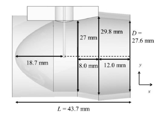
Fig. 11 shows another circular waveguide antenna structure with a curved short wall [25]. The curved short wall has a parabolic surface with
Fig. 12 shows the
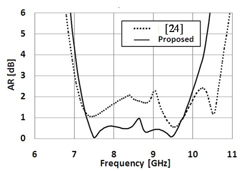
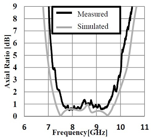
Fig. 15 shows the 3-dB AR characteristics. The AR bandwidth of the proposed antenna is narrower than that of the previous antenna; however, the AR value is lower than that of the previous antenna. This result indicates that XPOL in the boresight direction decreases.
Next, the reason why the AR at low frequency is reduced when the aperture is smaller is discussed. Fig. 13 shows the strength of the E-field distributions in the xy-plane at
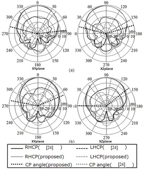
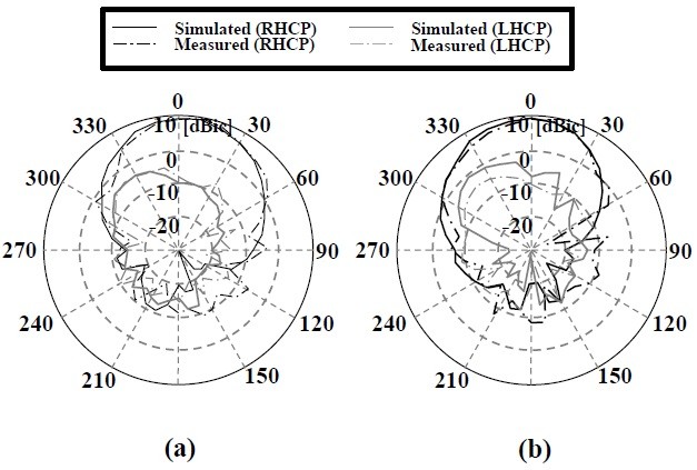
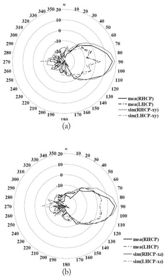
Fig. 14 shows the radiation patterns at 8 and 9 GHz. This figure shows a reduction in XPOL at both the boresight and off-boresight. Therefore, the angle range in which CP is generated is wider than that of the previous antenna.
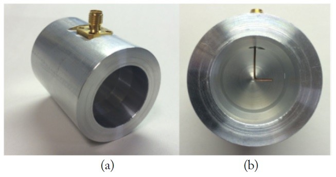
The simulation and experimental results of the proposed antenna are compared. Fig. 16 shows a photograph of the fabricated antenna. The antenna is made of aluminum, and the L-shaped probe is made of copper.
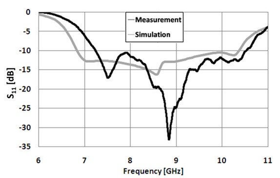
The measured and simulated
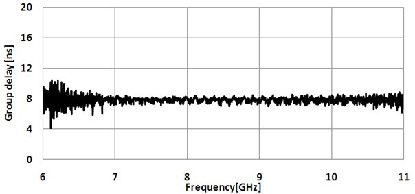
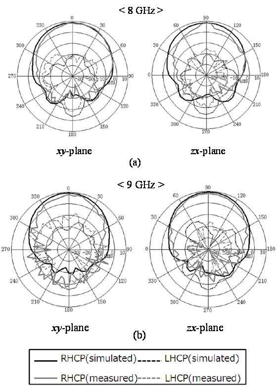
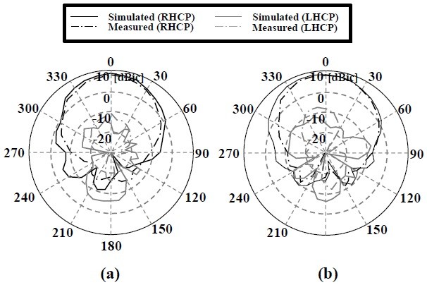
Fig. 19 shows the simulated and measured radiation patterns at 8 and 9 GHz. The measured and simulated results show good agreement at 8 GHz. The measured and simulated XPOL differ slightly; however, XPOL compared to that in [24], as shown in Fig. 8, is kept sufficiently low over a wide range of angles. Furthermore, Fig. 20 shows the mea-sured group delay characteristics in the boresight. The group delay remains almost constant with less than 1-ns variation. This indicates that the proposed antenna could be applied for UWB-high band applications.
The author has presented some recent results on broadband CP waveguide antennas using an L-shaped probe. This type of antenna can achieve high gain and constant group velocity in addition to wideband 3-dB AR and impedance characteristics. However, the L-shaped structure has an asymmetrical structure, resulting in high XPOL. The author has shown that XPOL can be reduced by using some techniques. This is partly due to the reduction of HOM, which has an asymmetrical, frequency-dependent distribution. Low XPOL results in a wide range of angles in the radiation pattern. The proposed antenna has 3-dB AR of around 45%, and the azimuth range for 3-dB AR is 100°–170° depending on frequency. Expanding the AR bandwidth while retaining the above advantageous characteristics is important for covering the UWB full band.


![Structure of antenna [18].](http://oak.go.kr/repository/journal/21347/E1ELAT_2017_v17n1_1_f006.jpg)


![Waveguide antenna using an L-shaped probe and parabolic short wall [25].](http://oak.go.kr/repository/journal/21347/E1ELAT_2017_v17n1_1_f011.jpg)