The Kyoto University Research Reactor Institute (KURRI) has engaged in innovative project of research and development of an accelerator-driven system (ADS) at the Kyoto University Critical Assembly (KUCA)[1]-[9] and an external neutron source. The main objective of the project is to develop a next-generation neutron source with the use of the ADS with high-energy protons obtained from the fixed field alternating gradient (FFAG) accelerator,[10]-[12] instead of the conventional research reactor (the Kyoto University Research Reactor: KUR; 5 MW) at KURRI. The basic concept of ADS was originally proposed as an energy amplifier system[13] that couples with a high-power accelerator and a thorium sustainable system. Another possible function of ADS was resolving the issue of nuclear transmutation of radioactive materials, including minor actinides and long-lived fission products. The current research activities on ADS involve mainly experimental feasibility studies with the use of critical assemblies and test facilities: MASURCA,[14]-[16] YALINA-booster and - thermal,[17]-[19] VENUS-1,[20] GUINEVERE[21] and KUCA.
In the ADS facility, a study on target design was requisite experimentally and numerically for examining the characteristics of spallation neutrons generated by injecting the high-energy protons before reactor physics experiments on feasibility studies of ADS. Especially dimensions of the target (size and thickness) needed to be investigated, before the actual injection of high-energy protons, because they are expected to vary in accordance with the spot and the energy of protons. The main characteristics of spallation neutrons analyzed experimentally and numerically at another irradiation facility[22] have contributed notably to the present study. On the basis of those valuable results, the present experimental study of spallation neutrons generated at the tungsten target was conducted, focusing on the neutron spectrum (reaction rates and continuous energy distribution of neutrons) at the location of the target. Special attention was paid to the reaction rates (neutron yield and profile) with the use of bismuth (Bi) and indium (In) activation foils, and to the continuous energy distribution of neutrons using organic liquid scintillator. These experiments on continuous energy distribution of neutrons were emphasized to be carried out near the location of the target, whereas neutron spectrum measurements are usually conducted by the time of flight method at a location far from the neutron source. Further, the neutron spectrum measurement was considered difficult near the location of the target, because the accuracy of neutron detection is dependent on two factors: the distance and the time of flight of neutrons.
The neutron spectrum was considered an important parameter for recognizing information on neutron energy at the target; as a result, the experimental analyses at the target could significantly affect the neutronic characteristics of the core by numerical analyses in the feasibility study on ADS. Also, the neutron spectrum evaluated by reliable methodologies could contribute to accurate prediction of reactor physics parameters in the core through numerical simulations of desired precision. The objective of this study was to analyze experimentally the neutron spectrum of spallation neutrons generated by 100 MeV protons at the location of the target in the ADS facility, before the actual operation of ADS and the improvement of numerical simulations. The neutron spectrum experiments with 100 MeV protons generated by the FFAG accelerator are shown in Sec. 2 and include descriptions of the experimental settings. The results of experimental and numerical analyses by the Monte Carlo calculation code combined with nuclear data libraries are presented in Sec. 3 and the conclusions are summarized in Sec. 4.
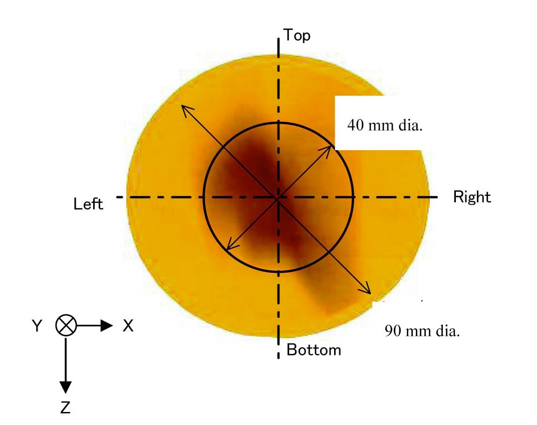
High-energy protons were generated by the FFAG accelerator under the following parameters: 100 MeV energy; 30 pA intensity; 30 Hz repetition rate; 200 ns beam width. On the downstream of the FFAG beam line, the tungsten was set at the location of the original target (80 mm diameter and 10 mm thick); the thickness was determined on the basis of previous experimental and numerical analyses[22] for the injection of high-energy proton beams onto the tungsten target. For the proton beam configuration modeled by numerical simulations, the size of the proton beam spot was requisite experimentally and precisely, when 100 MeV protons were injected onto the tungsten target where the spallation neutrons are generated. The Gafchromic film,[23] which is very sensitive to the charged particles, was then used to evaluate the size of the proton beam spot injected onto the tungsten target, since a graphic image on the film is acquired quickly after the irradiation of charged particles for a short time.
The reaction rates for threshold energy of high-energy neutrons and the continuous energy distribution of the spallation neutrons at the target were acquired by the foil activation method and the organic liquid scintillator, respectively. The high-energy neutrons (spallation neutrons) of threshold reactions 209Bi(
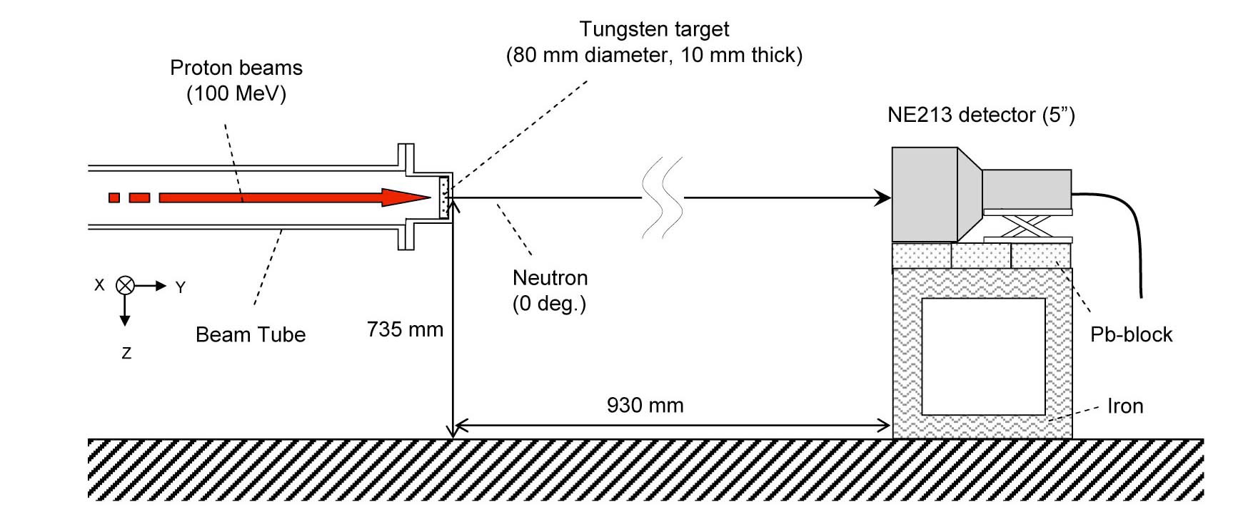
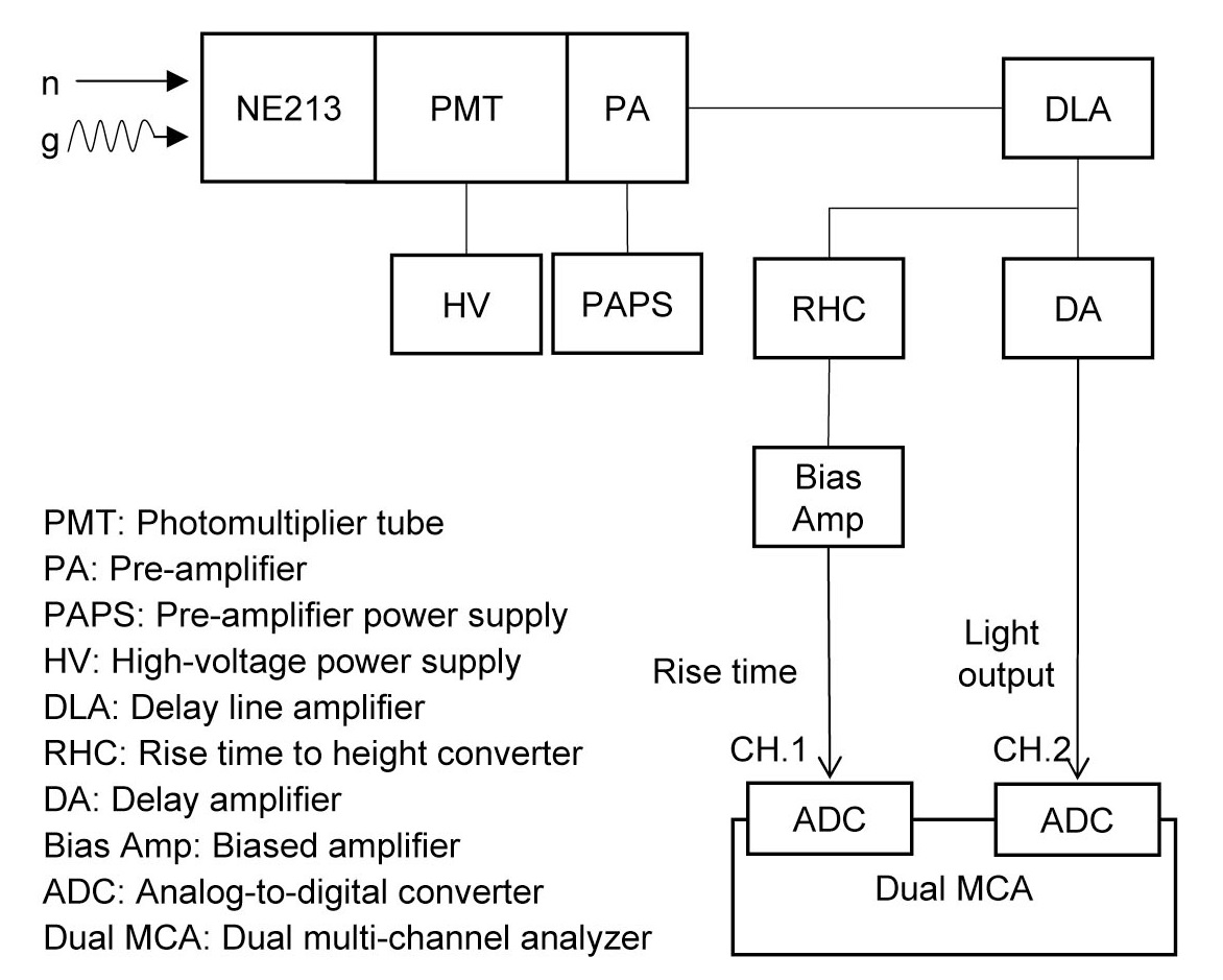
The continuous energy distribution of spallation neutrons was determined by the organic liquid scintillator (Nuclear Enterprises Ltd., NE213 Scintillator; 5” in diameter and 5” long) set directly facing the tungsten target without any reactor components as shown in Fig. 2(a). The measurement circulation of the organic liquid scintillator was as indicated in Fig. 2(b). The main advantage of the measurement system is that the two signals (rise time and light output of
The 10 mm thick tungsten target was determined on the basis of experimental and numerical analyses[22] from the viewpoint of the full-stop of proton beams within the tungsten target. On the other hand, the proton beam irradiation experiments were carried out to monitor the size of

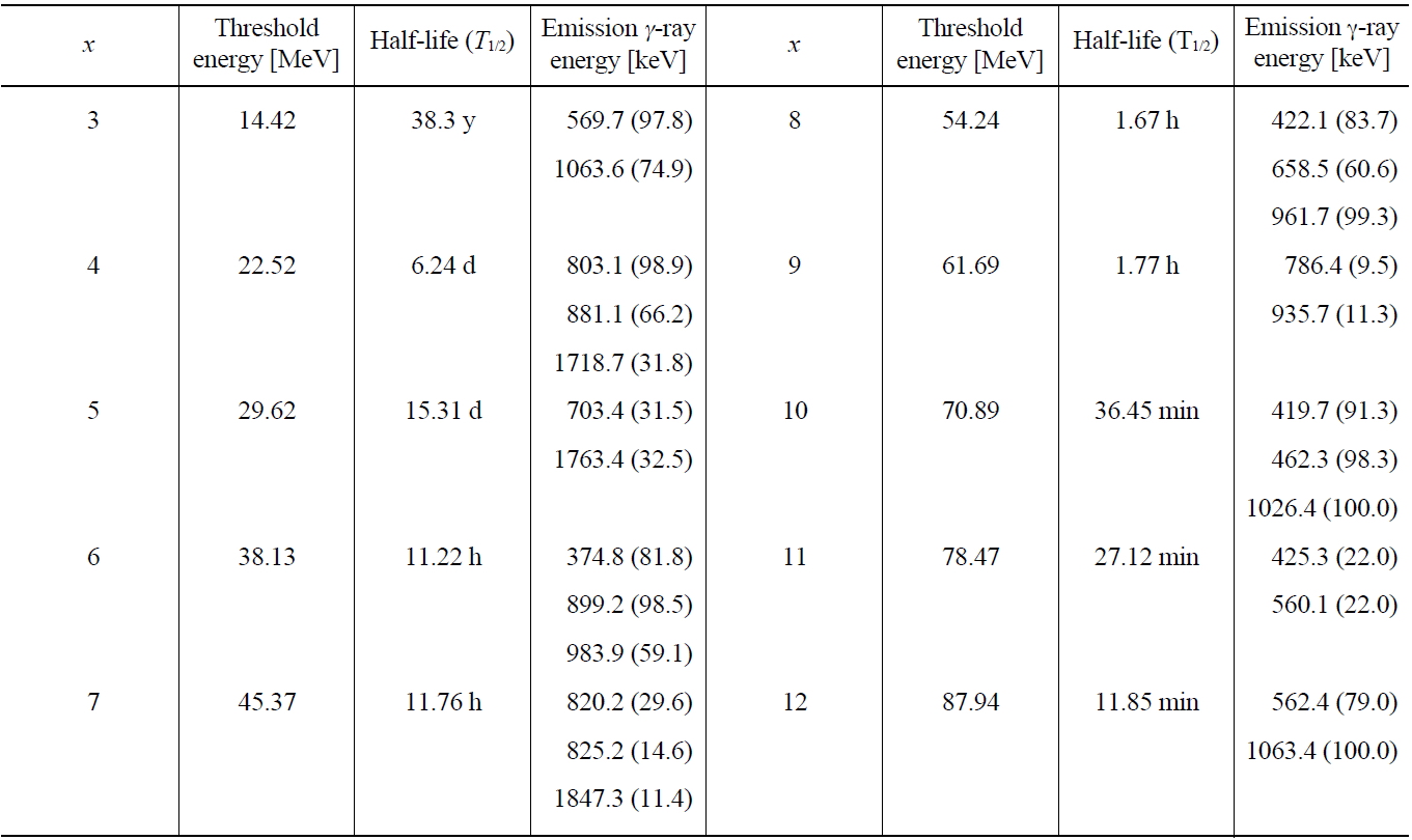
Threshold Energy, Half-life and γ-ray Energy of 209Bi(n, xn) 210-xBi Reactions (x = 3 to 12)
[Table 2.] Threshold Energy, Half-life and γ-ray Energy of 115In (n, n’)115mIn Reactions
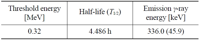
Threshold Energy, Half-life and γ-ray Energy of 115In (n, n’)115mIn Reactions
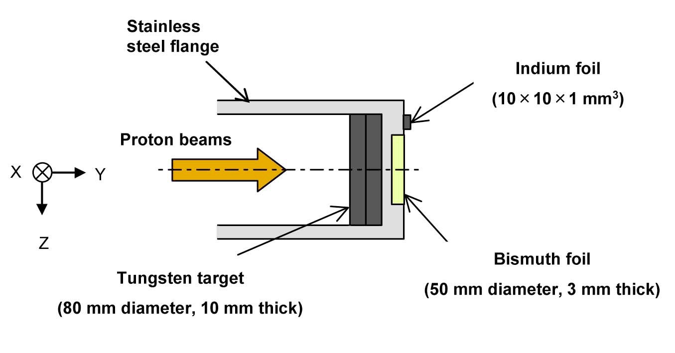
the proton beam spot with the use of Gafchromic film, which is highly-sensitive to charged particles. The Gafcromic film was irradiated for two min and set on the surface (downstream beam) outside the stainless steel flange (Fig. 1)
[Fig. 1(b).] Experimental Setting of Tungsten Target for Angular Distribution of Spallation Neutrons
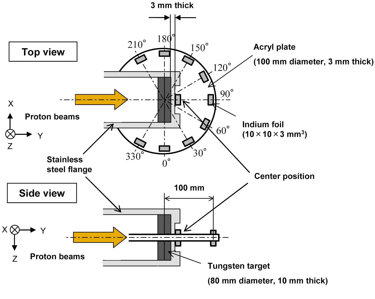
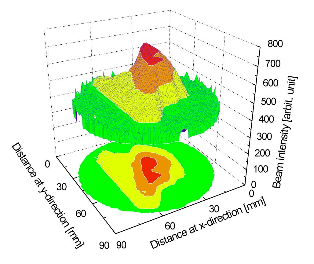
without the tungsten target, although the influence of the stainless steel flange was slightly affected to the proton beam profile. It demonstrated that the proton strength was distributed by the downstream beams (Fig. 3(a)), with a relative distribution within an approximately 40 mm diameter spot (Fig. 3(b)). The experimental result of the Gafchro-
mic film was very useful for modeling the size of the proton beam spot in numerical simulations, therefore, the irradiation experiments were important for evaluating the size of the proton beam spot for which the tungsten target (80 mm in diameter) was considered sufficient to cover.
The experimental results of the reaction rates were obtained by measuring total counts of the peak energy of
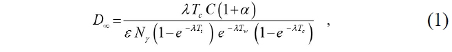
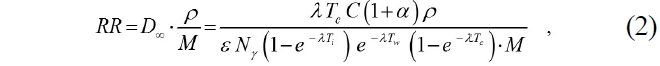
where
No value for the 100 MeV proton irradiation was observed in 3
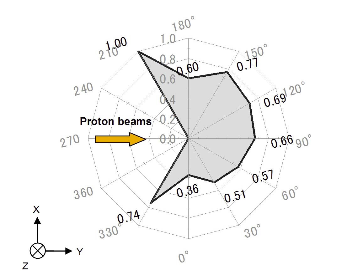
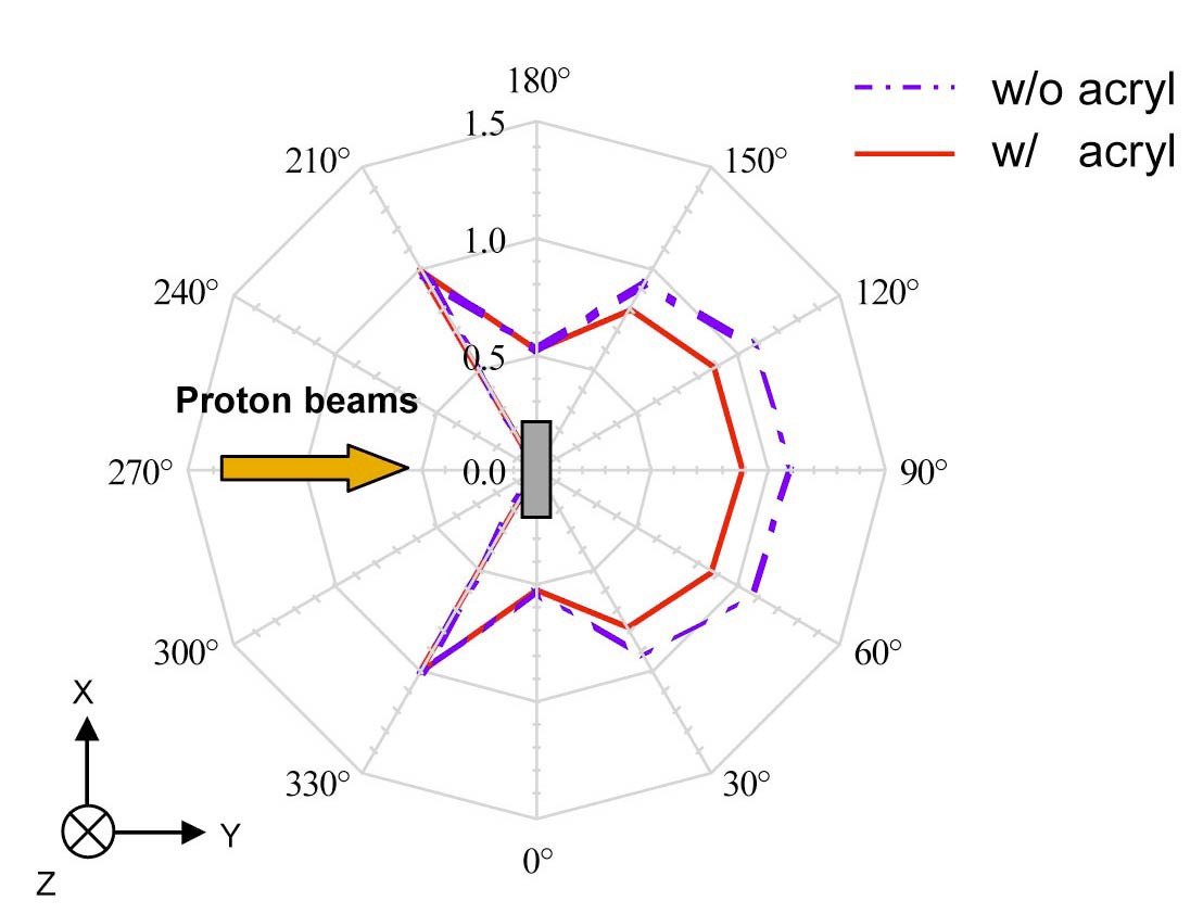
The measured results of the 115In reaction rates for the angular are listed in Table 4. The highest reaction rate was observed at the center of the tungsten target shown in Table 4, and the angular distribution (Fig. 4(a) and Table 4) of reaction rates appeared slightly polarized in the upper direction, when all reaction rates were normalized by that at position 210 degrees, which was the largest along the angular. The reaction rate at 210 degrees was larger than at other positions, whereas the effect of the acryl plate was considered insufficient in the measured reaction rates along the angular. Next, to investigate the effect of acryl plate on measured reaction rates, numerical simulations were executed with the use of MCNPX and JENDL/HE-2007 with (w/ ) and without (w/o) the acryl plates. A comparison of the results (Fig. 4(b)) in the presence or absence of acryl

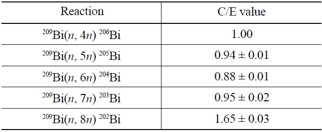
C/E Values between Measured and Calculated Reaction Rates of 209Bi(n, xn)210-xBi Reactions (x = 4 to 8) for 100 MeV Proton Beams
[Table 4.] Measured Results of Indium Reaction Rates for the Angular
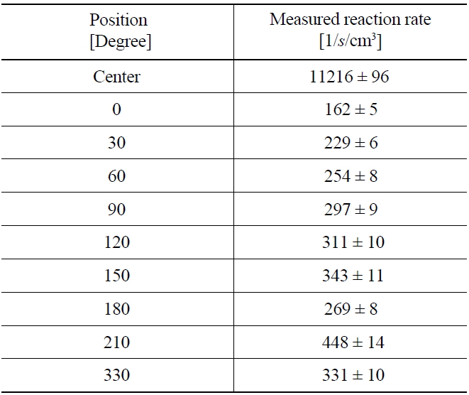
Measured Results of Indium Reaction Rates for the Angular
plates showed an apparent effect on the reaction rates: the high-energy neutron flux was attenuated ahead at the target and influenced by the acryl plate. Thus, the spallation neutrons were considered significantly spherical in the angular distribution through the results in numerical simulations, although their angular distribution was observed actually reversed at the target. Subsequently the neutron yield at the target was evaluated at (9.73±0.12)×104 1/
3.3 Continuous Energy Distribution
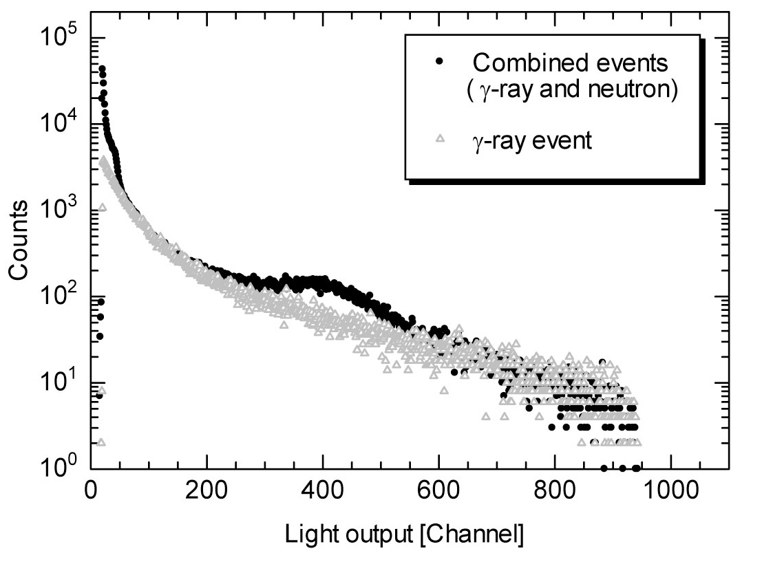
The main characteristics of the measurements by the organic liquid scintillator are to acquire two signals of prompt (electrons) and delayed (protons, deuterons, or α-ray, etc.) fluorescence components and to discriminate
A comparison between the combined (
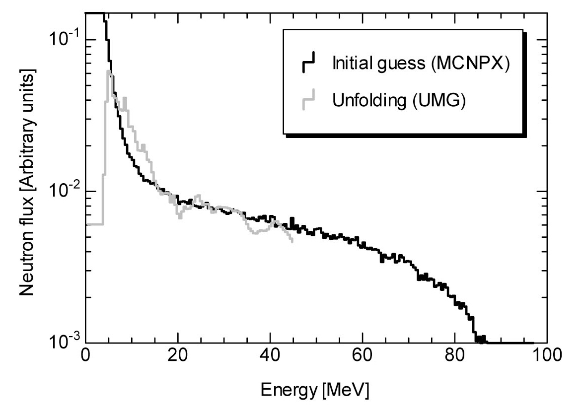
The neutron spectrum (Fig. 6) was obtained experimentally with the use of the SCINFUL-QMD code[29] for the matrix of response functions and with the UMG code[30] for the unfolding of experimental results (Fig. 5) together with the matrix by SCINFUL-QMD. As a reference of the neutron spectrum, the MCNPX calculations were executed with the use of ENDF/B-VI.6[31] for cross section data and of LA150[32] for the high-energy neutron and proton libraries. A comparison between the experiment (UMG) and the calculation (MCNPX) revealed an approximate reconstruction of the neutron spectrum in the experiment, ranging between 5 and 45 MeV neutron, although the discrepancy was observed in some energy regions. In the measurement system, the amount of fluorescence was insufficiently over 50 MeV neutron, because of detector sensitivity in relating the intensity and the energy of protons. Finally, the spallation neutrons up to 45 MeV were considered successfully detected by the organic liquid scintillator, since the discrimination
[Fig. 6.] Comparison between Measured (Unfolding) and Calculated (MCNPX) Results of Neutron Spectrum
between the
Neutron spectrum experiments on spallation neutrons were conducted in the ADS facility at KUCA to investigate the neutronic characteristics of spallation neutrons generated at the target. The reaction rates and the continuous energy distribution of spallation neutrons were measured by the foil activation method and by the organic liquid scintillator, respectively. For the reaction rate experiments of 209Bi foil, the C/E values between the experiments and the calculations (MCNPX and ENDF/B-VI) were found well within the relative difference of 10% (209Bi(