The accident at the Fukushima Daiichi nuclear power plant in 2011 has become an unfortunate landmark in the history of nuclear power. The flooding of the emergency diesel engines and batteries by a colossal tsunami caused a long-duration total station blackout and disabled the cooling of the cores. This led to the meltdown of the core and the release of fission products in units 1, 2 and 3 of the plant. This tragic accident has raised various issues on every aspect of the safety of nuclear power.
Although the possibility is considered very low, the failure of the reactor vessel and subsequent discharge of the molten core mixture or corium is a possible consequence resulting from a severe accident. As the only safety measure once the core-melt discharges, the ex-vessel corium must be retained and cooled down in a dedicated area within the containment building. Such equipment is called an ex-vessel core-catcher. Among the various concepts developed during the past several decades for pressurized water reactors [1], two concepts have been realized in nuclear power plants. The first concept was applied to the two VVER 1000-91/99 units of Tian Wan (China) [2]. In this concept, a crucible-type catcher filled with a lot of sacrificial materials is located below the reactor vessel to confine the corium melt released during a severe accident. The melt relocates into a steel vessel and is cooled by water flowing outside the vessel and onto the melt surface. The interaction of the corium with a unique sacrificial material forms an oxidic melt surface onto which water can be directly supplied. The second concept has been applied to EPR design, which has a melt discharge channel under the reactor guiding the ex-vessel corium into a spreading compartment with sacrificial material [3,4]. The arrival of the melt in the core-catcher triggers the supply of water to fill in below and around the compartment in a passive mode, which eventually pours onto the surface of the melt. The EPR reactor of the Olkiluoto (Finland) plant (Unit 3) is currently under construction. In addition, the COMET concept of Forschungszentrum Karlsruhe (FZK) was developed to quench and crack the melt by water injected from the bottom [5]. The melting of the sacrificial concrete substrate initiates the ingression of water through an array of tubes or porous concrete at a slight overpressure in this concept, but it has not been realized in a nuclear power plant yet.
For the development of a core-catcher, a number of stages are required to evaluate its performance for various accident scenarios leading to the rupture of the vessel. Firstly, the mode of vessel rupture is analyzed from accident scenarios to predict the time, amount, composition and decay heat level of the ex-vessel core melt. Then, the dynamic behavior of the corium is predicted to determine the relocation time, flow pattern and height inside the core catcher. For the stage at which it is confined in the corecatcher, the cooling of the corium is investigated. In these steps, the details of the thermo-chemical behavior of the corium should be considered, including its interaction with the sacrificial substrates, transient heat transfer with the coolant, and corresponding changes in the melt composition and properties. The results for the generation of steam, hydrogen and other gases from the corium-concrete interaction in the core-catcher are used to predict the gas flow, pressure, composition and temperature in the containment vessel. Using this information, the structural integrity and survivability of the containment vessel can be evaluated.
Understanding the dynamic behavior of corium in a core-catcher requires the consideration of the flow, phase and chemistry involving the interactions with the sacrificial substrate, subsequent changes in the physical properties of the corium, and various modes of heat transfer. The spreading of corium has been studied experimentally at dedicated facilities with simulants using molten metals (CORINE [6], S3E[7], SPREAD[8]), oxides (KATS[9], ECOKATS[10]) or prototypic corium (COMAS [11], FARO [12], and VULCANO[13]). Among these, a series of extensive tests were carried out using the VULCANO facility with simulants mainly composed of HfO2 and prototypic corium using depleted UO2 at temperatures above 1800℃. The results from these tests include the propagation and spread profiles of corium in channels with ceramic or concrete substrates, ablation of the concrete substrate, heat transfer and post-mortem micro-structural analysis.
In parallel with these experimental studies, computational models have also been developed for the spreading of corium [14]. The modeling codes available for the prediction of corium spreading include THEMA [15], LAVA [16], CROCO [17], MELTSPREAD [18] and CORFLOW [19]. These codes have modeling features dedicated to the fluid dynamics or physico-chemical behavior of corium [14]. For example, the non-Newtonian flow and rheological property changes of corium are considered in these codes. Also, most of these codes can predict the formation of a crust at the top and bottom and its interaction with the concrete substrate, such as the emission of gases. However, such codes are limited in their modeling capability for complex 3-dimensional geometries or the detailed flow and heat transfer characteristics including the gas phase.
On the other hand, general-purpose commercial CFD codes such as FLUENT and CFX provide powerful features on a wide variety of flows involving multi-phases, chemical reactions and heat transfer; however, specific submodels for the physical properties or reactions required for corium spreading predictions are not available. Also, access to the source code of such packages through user-defined subroutines, which is necessary for the full implementation of specific sub-models, is highly limited.
In this paper, numerical simulations of corium spreading conducted with FLUENT are presented as a means of evaluating the commercial CFD code for the application to a core-catcher design requiring a 3-dimensional modeling feature. The VULCANO VE-U7 corium spreading test was used as the reference data. In the simulations, the physical properties of corium such as its viscosity were considered through a user-defined subroutine in the code. The effects of radiative heat transfer, the temperaturedependence of the viscosity, decay heat and initial temperature on the spreading of corium were investigated with a detailed discussion on the temperature profile, viscosity and heat transfer.
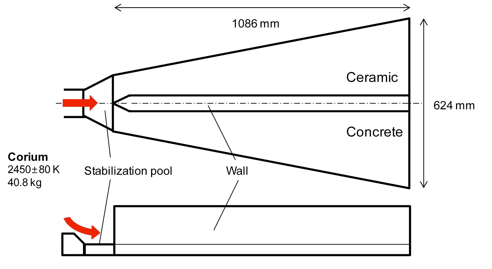
The spreading of ex-vessel corium was extensively studied by Journeau et al. [13] using the VULCANO facility [20] with a corium surrogate containing HfO2 and prototypic corium containing depleted UO2. The present study uses the data collected from the VULCANO VE-U7 test, which includes the temperature, heat flux, spreading heights and front positions of corium. In this test, the corium consisted of UO2 (61 wt.%), ZrO2 (30 wt.%) and other oxides, which have a liquidus temperature of 2375 ℃ and a solidus temperature of 1000 ℃. About 40 kg of corium at 2175±75 ℃ entered the spreading section shown in Fig. 1 which was divided into two channels made of zirconia bricks with ceramic or concrete substrates, respectively. A total of 12.6 kg flowed into the channel on the concrete for about 7 seconds and 14 kg flowed into the channel on the ceramic for about 12 seconds, forming
spreads with lengths of about 350 mm and 470 mm, respectively. The height of the spread after consolidation was about 60-65 mm with a bulk density of 5000±200 kg/m3. The solid volume fraction at this temperature was estimated to be about 50% [21].
Since the spreading of corium follows unsteady twophase flow behavior in an open channel, the volume-offluid (VOF) method [22] is appropriate. This method solves a single set of momentum equations in a fixed Eulerian mesh tracking the interface between the phases based on the volume fraction in each control volume. In the VOF method, the continuity equation for the volume fraction of the primary phase (gas) without mass exchange with the secondary phase has the following form.
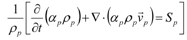
The source term Sp becomes 0 unless the mass source is specified. The volume fraction of the secondary phase (corium, αs) is computed based on the remainder of the volume fraction:
The geometric reconstruction scheme [23] was applied for interface (free surface) tracking, which assumes a piece-wise linear shape of the interface based on the volume fractions of the two phases.
For the convection-induced turbulent flow in the gas phase, the standard k-ε model was applied for improved stability and convergence, although a higher order model such as Reynolds stress model would provide more accurate results if the focus were on the gas phase flow.
For the radiative heat transfer calculations, the discrete ordinate method (DOM) [24] was applied, which solves the radiative transfer equation for a finite number of discrete solid angles. The number of angles discretized was 5 both in the polar and azimuthal directions. The absorption coefficient of a material determines the exponential attenuation of the radiation intensity through it. Its value for corium was assumed to be very large (10000 m-1) so that only its surface emits radiation to the surroundings. The gas was transparent to radiation (absorption coefficient: 0 m-1).
2.3 Physical Properties of Corium
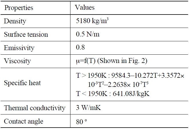
Table 1 lists the physical properties of corium, which were collected from the report of Journeau et al. [21]. The bulk density of corium was 5180 kg/m3, which includes the effect of the variation of the porosity in the range from 28 to 32%. The measured specific heat was fitted into a temperature dependent polynomial, as shown in Table 1 for the range of temperatures of 1900-2500K. The value under this range was considered to be constant, since the temperature of corium during computation did not fall below 1900K. The thermal conductivity, emissivity and surface tension of corium were constant at 3 W/mK, 0.8 and 0.5 N/m, respectively. The contact angle of corium on the substrate and the wall was assumed to be 80° based on the profile of the spread height after consolidation.
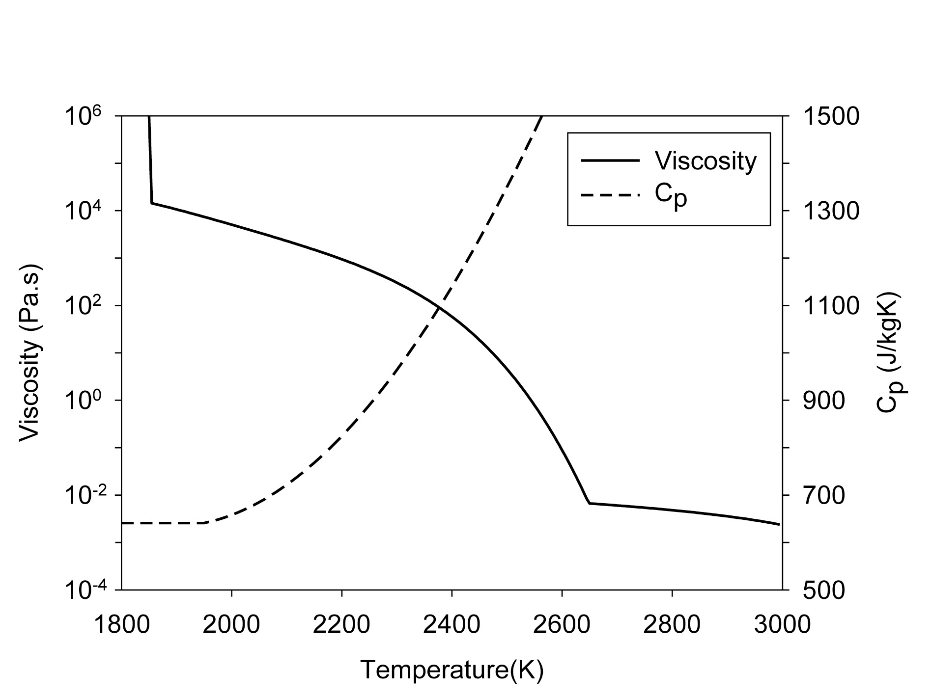
The viscosity of corium is a critical physical property that is strongly temperature-dependent and influences the flow pattern. The model proposed in Journeau et al. [21] used the following correlation:
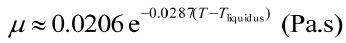
with the two limiting values shown below.
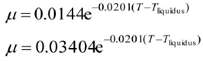
The viscosity based on the above correlations is plotted in Fig. 2, together with the specific heat. According to this model, the viscosity of corium at the inlet (at 2450K) becomes 18.6 Pa·s, as a result of which the spreading
[Table 1.] Physical Properties of Corium Considered

Physical Properties of Corium Considered
would be in the viscosity-dominated regime rather than the inertia regime. The viscosity model was inserted into the CFD code (FLUENT ver. 6.3) through a user-defined subroutine.
The physical properties of the gas phase were those of nitrogen, in which the density was calculated as that of an incompressible ideal gas, and the other properties (specific heat, viscosity, conductivity) as functions of temperature.
2.4 Geometry and Boundary Conditions of Computational Domain
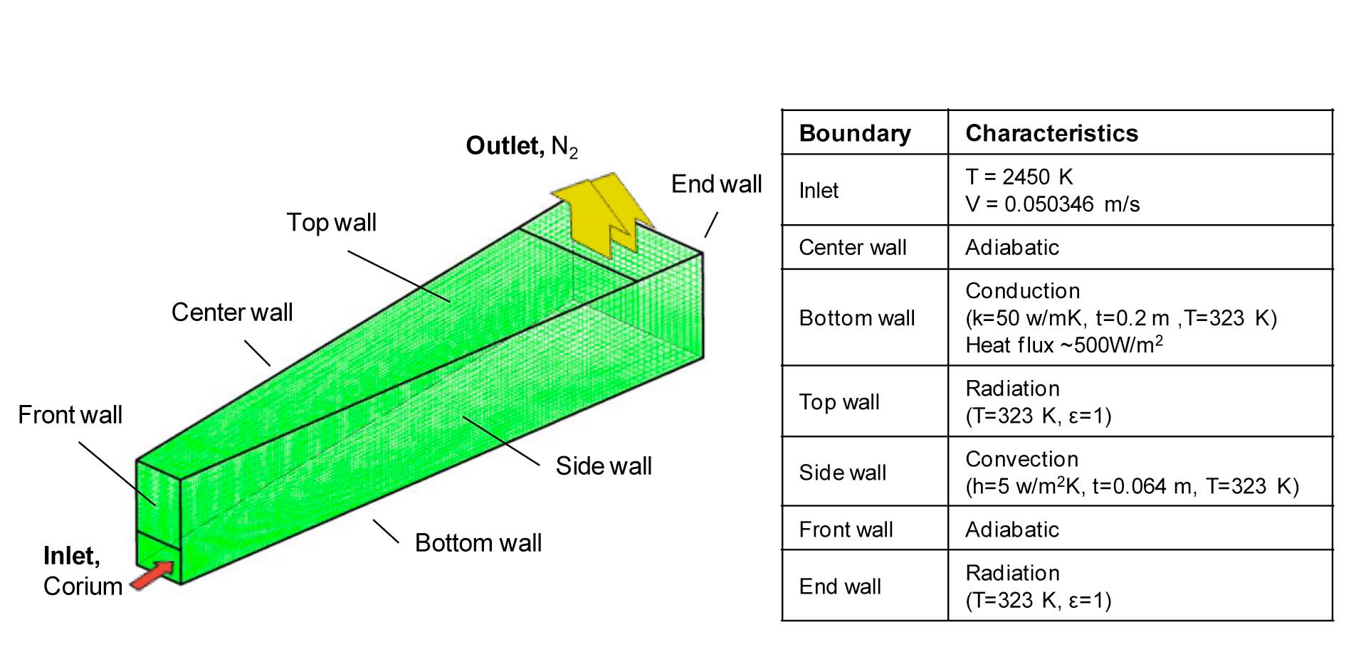
Fig. 3 shows the geometry of the channel with the boundary conditions of the computational domain. Only one of the two symmetric channels in Fig. 1 was considered. The channel was 95 mm wide at the corium inlet and 280 mm at the other end with a constant height of 150 mm. The volume was initially filled with gas at 300 K, and corium at 2450 K entered from the inlet with a height of 65 mm. The velocity of corium was 0.0503 m/s and was maintained for 7.7 seconds, which corresponds to 12.4 kg of corium entering into the channel on concrete in the VULCANO VE-U7 experiment [13,21].
The bottom wall of the channel had a conductivity of 50 W/m2K and a thickness of 0.2 m in order to address the conductive heat loss of ~500 kW/m2 from the corium that represented the average heat flux measured during the experiment [13]. Note that directly prescribing the heat flux on the bottom wall leads to the inappropriate cooling of the gas in the downstream. For a comprehensive simulation, the substrate layer should be included in the computational domain to consider the transient conduction, while the base material below the substrate is considered as a boundary wall for conduction. However, this study focused on assessing the capability of the CFD code for a number of parameters associated with the properties of corium.
The channel had an open top in the actual test, but was assumed to be enclosed by a wall except for the outlet section toward the other end of the channel. The reason for this simplification was that the continuous inflow and outflow of the gas by convection across the top boundary made the computation unstable if the boundary was fully open. The temperature and emissivity for the top wall were set to 323K and 1.0, respectively, so that the radiative heat loss to the surroundings could be predicted.
The domain was discretized with 22 150 30 hexahedral cells, as shown in Fig. 3. For the time-dependent simulations, an explicit time discretization was used with a fixed time step of 0.001s for a total of 7.7 seconds.
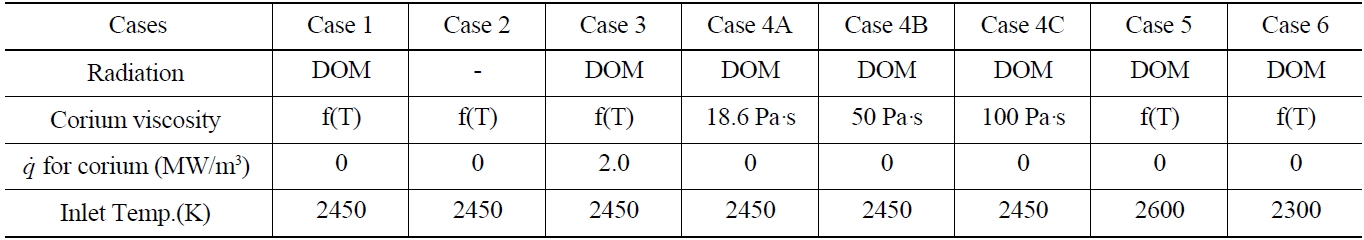
The effects of the key parameters on the corium spreading were investigated for the corium viscosity, radiation, decay heat and inlet temperature. Table 2 lists the selected cases of simulations. Case 1 is the reference case where the radiation and the temperature-dependent variation in viscosity of corium were considered. In Case 2, radiation was not included in order to understand its effect by comparison with Case 1. In Case 3, an indicative value of the decay heat of 2.0 MW/m3 was considered for corium, although the VULCANO VE-U7 used depleted corium. This value was estimated using the decay curve model [25] shown below.
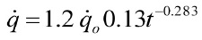
The initial power

used in the estimation was 160 MW/m3 which represented 200 tons of core-melt in a 4000 MWth capacity plant at a density of 8000 kg/m3. The above-mentioned value corresponds to 7200 sec (2 hours) after the core melt-down. Since the heat release is only for the volume occupied by corium in the computational domain, the volume fraction of corium needs to be multiplied to the above-mentioned value. This was programmed into the CFD code using a user-defined subroutine.
Cases 4A, 4B and 4C had viscosities of corium fixed at the inlet value (18.6 Pa·s), near-average (50 Pa·s) and very large (100 Pa·s), respectively, instead of the temperaturedependent values. In Cases 5 and 6, the inlet temperature of corium was changed to 2600 K and 2300 K, respectively, from 2450 K in the reference case.
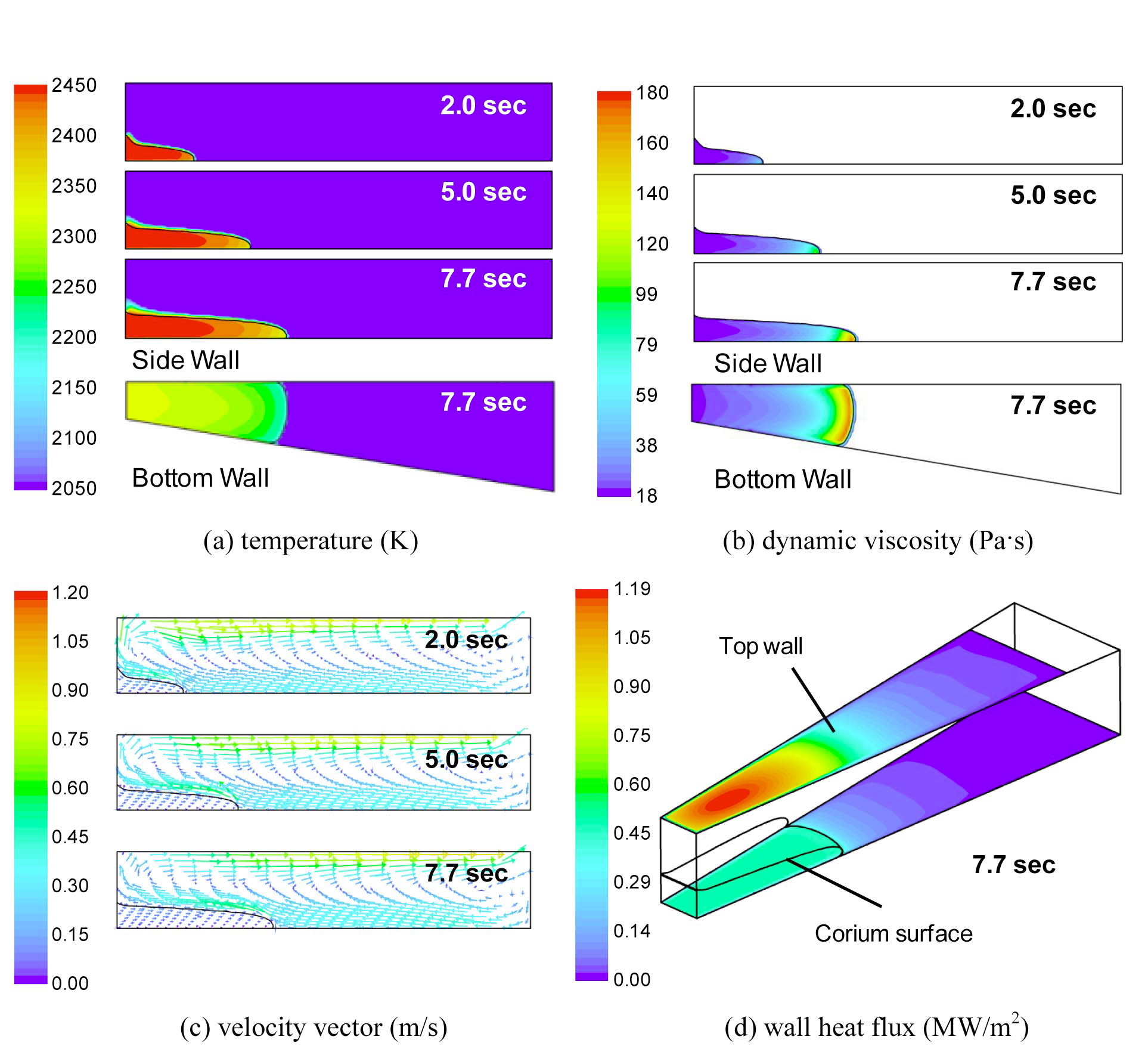
3.1 Simulation Results for the Reference Case (Case 1)
Fig. 4 illustrates the temperature, viscosity, velocity vector and wall heat flux for Case 1 at different computation times. In this figure, the thick black line indicates the interface between the corium and the gas. The corium
[Table 2.] Simulation Cases for Spreading of Corium

Simulation Cases for Spreading of Corium
propagated toward the other end of the substrate and the natural convection induced a rapid temperature increase and strong upward flows of the gas. The temperature at the front of the corium gradually dropped to 2336 K at t=7.7 sec. This led to an increase in the viscosity of corium from 18.6 Pa·s at the inlet to 178.5 Pa·s at the front. The temperature in the vertical cross-section near the corium front had a parabolic profile, in which the temperature dropped toward the top surface by radiation and convection, and also toward the bottom by conduction. In Fig. 4c, the gas velocity was much larger than that of corium, especially in the horizontal flow along the top wall towards the exit. This induced an opposing gas flow against the corium. However, this was not expected to retard the progress of corium, since its momentum (mass x velocity) was much larger than that of the gas. In Fig. 4d, the heat flux at the top wall at t=7.7 sec was as large as 1.2 MW/m2, due to the radiation from the hot corium surface. The bottom wall covered by corium had an almost constant heat flux of 0.5 MW/m2 through conduction, which was prescribed by its boundary condition as described previously. The bottom wall in front of the corium also had an outward heat flux by radiation which rapidly decreased as the distance from the corium increased. The convection to the gas was estimated to be 0.03-0.04 MW/m2 with heat transfer coefficients ranging from 15 to 19 W/m2·K, which is not significant compared to the other modes of heat transfer.
3.2 Effects of the Properties of Corium
Fig. 5 compares the profiles of the temperature and dynamic viscosity for the simulation cases at 7.7 sec along the center-line of the corium. The corium in Case 2 shown in Fig. 5a stayed almost isothermal at 2450 K except for the front, since the radiative heat loss was not considered. This case also had a temperature distribution of the corium in the vertical direction which decreased only toward the bottom by conduction, unlike that of Case 1 which formed a parabolic profile. The corium front had a temperature of 2420 K with a viscosity of 37.8 Pa·s. As a result, the corium front at t=7.7 sec progressed 66.5 mm farther than that in Case 1. Fig. 5a also shows the results of Case 3 (with decay heat), which were very similar to those of Case 1. For a corium density of 5180 kg/m3 (
on the rate of increase of temperature corresponds to a value of merely 0.515 K/s
The resultant temperature increase is less than 4 K for 7.7 seconds. This explains why the decay heat in Case 3 did not noticeably influence the corium spreading in Fig. 5a. Therefore, the effect of decay heat is not critical in the short-term behavior of a shallow corium flow.
Figs. 5b show the influence of the viscosity on the speed of corium progression when the viscosity of corium was fixed at 18.6, 50 and 100 Pa·s. Although these three values of viscosity were within the range that appeared in Case 1, significant differences were observed in the speed and spread profile of the corium progression. In Case 4A with a corium viscosity of 18.6 Pa·s, the corium collapsed near the inlet into a thinner spread profile, due to gravity, and progressed much faster. The increase in the surface area of the corium led to a lower temperature at the front. In contrast, Case 4C with 100 Pa·s showed an increase in the height near the inlet, due to the larger resistance to the progression caused by the high viscosity. The results of Case 4B were similar to those of Case 1. However, the two cases had differences in velocity history, which will be presented in the next section.
Fig. 5c shows the results for Cases 5 and 6 for different inlet temperatures. With an initial temperature of 2600 K in Case 5, the corium front progressed 0.22 m farther than in Case 1. This led to a thinner layer of corium on the substrate and a larger temperature difference between the inlet and the front (about 180 K in Case 5 and 110 K in Case 1). In contrast, Case 6 for the inlet temperature of 2300 K had viscosities of the order of 100 Pa·s which significantly slowed down the spreading of the corium. The corium front at 7.7 sec was located at 0.28 m from the inlet, which is 0.12 m less than in Case 1. The temperature at the front was 2216 K, which is 84K lower than the inlet value.
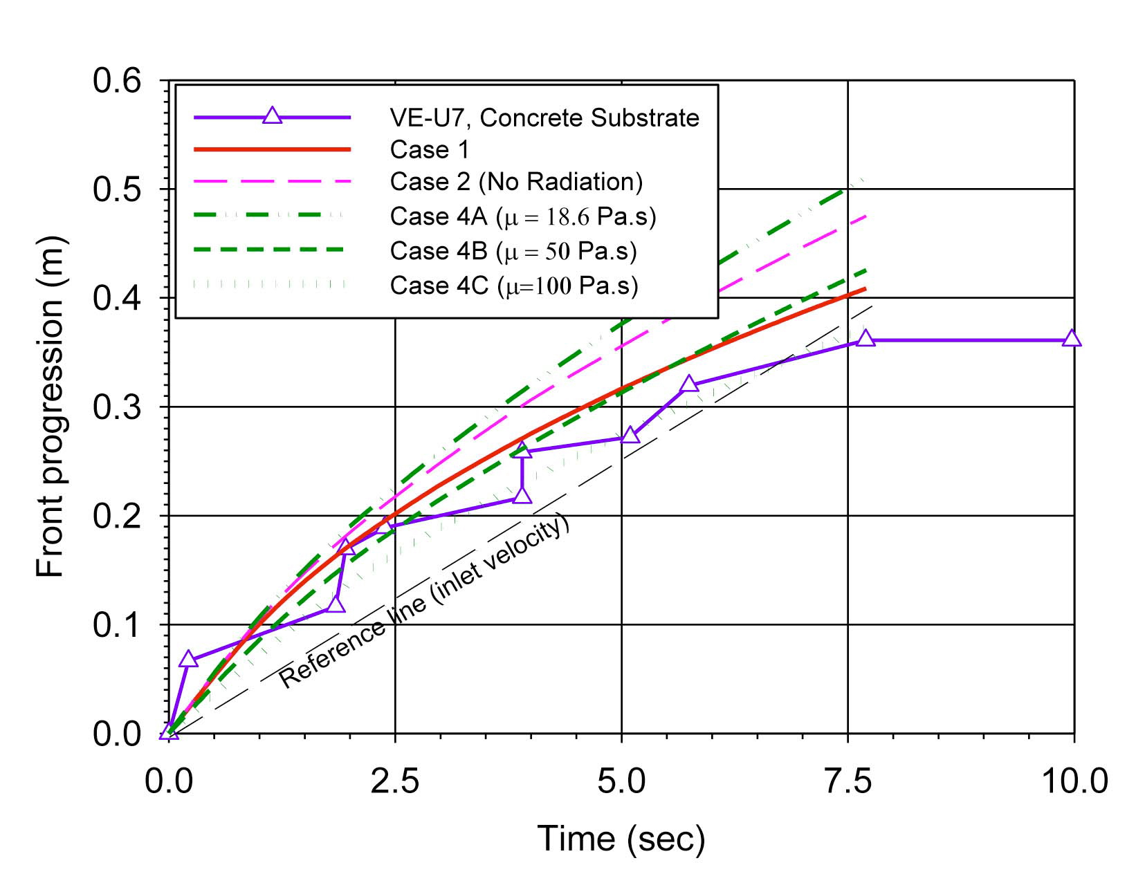
Fig. 6 compares the progress of the corium front in the different simulation cases to the experimental data on a concrete substrate [21]. A reference line is also plotted, which corresponds to the inlet velocity of corium. The propagation gradually slowed down both in the experimental and simulation data. The trend of corium progression in Case 1 was in reasonable agreement with the VEU7 test data, although the corium propagated with irregular steps during the test. These irregular steps could be associated with the formation of crust on the surface of the corium and its interaction with the concrete. The meltinduced erosion of the concrete substrate releases the gases through the corium. This changes the viscosity and mixes the surface boundary layers with the interior of the melt, which slows down the spreading of the corium and influences the surface morphology. The crust is recognized as a thin solid layer of solidified corium formed on the surface and at the interface with the substrate as a result of cooling. It interferes with the flow of the liquid corium and also significantly hinders the heat transfer. Ideally, this crust can be treated as a thin boundary surface of corium with a very high viscosity and low conductivity. However, it was difficult to predict in the generalpurpose CFD code.
Case 2 (no radiation) exhibited a significant overprediction in the progression of the front. This shows the important role of radiation in the cooling of the corium and corresponding increase in the viscosity. The result for Case 3 (not shown in Fig. 6) was almost identical to that of Case 1, since the temperature increase in the corium caused by the release of the decay heat was small, as described previously.
Cases 4A, 4B and 4C exhibited a wide variation in the front progression depending on the viscosity. Therefore, a temperature-dependent viscosity model is critical in predicting the spreading behavior of corium. Case 4B (μ = 50 Pa·s) has a curve close to that of Case 1, but there was a difference in the slope of these two curves. The
front progression in Case 4B was slower in the early stage, due to the higher viscosity, and became faster than that in Case 1 after t = 6 sec as the viscosity at the corium front in Case 1 exceeded 50 Pa·s. The front progression in Case 4C (μ = 100 Pa·s) was the slowest. It lies close to the experimental data in Fig. 6, but the value of the viscosity was arbitrarily selected only for comparison purposes.
The spreading of corium in a channel was predicted by FLUENT to evaluate the capability of the generalpurpose CFD code against the experimental data of VULCANO VE-U7. The effects of the key parameters were evaluated for the corium spreading, including the radiation, decay heat, temperature-dependent viscosity and initial temperature of corium. The simulated results showed reasonable agreement with the test data. Detailed information on the flow characteristics of both the liquid and gas were acquired, including the temperature and viscosity profiles of corium. However, the predicted results corresponded to the smooth and continuous progression of corium, unlike the test data which showed irregular steps during the progression. Further development on modeling is required to consider the flow and heat transfer effects by the formation of crust on the surfaces and its interaction with the substrate.
Symbols
S source term, kg/m3s
T temperature, K

volumetric heat release rate, MW/m3
t time, sec
v velocity, m/s
Greek
α volume fraction
μ dynamic viscosity, Pa·s
ρ density, kg/m3
Subscript
o Initial
p primary phase (gas)
s secondary phase (corium)