Achromatization is a necessary process to design a lens system which operates at various wavelengths or wavelength bands. Many achromatization methods based on the thin lens approximation and dispersion constants have been introduced in optical texts and monographs dealing with optical system design [1-3]. In addition to the chromatic variation, the change in ambient temperature affects the first order properties and aberrations of optical imaging system. Hence, various design methods which correct the chromatic variation and the thermal change at the same time have been presented [4-6]. In either case, the main purpose of the achromatization is to minimize image degradation due to chromatic variation within a specified wavelength range [7-9]. Since the refractive index of optical material varies rapidly in the blue region around 400 nm, expensive abnormal glasses are used to correct the chromatic variations in the blue region. For some applications, one wants a lens system which has good imaging performance at the blue region but is not necessary for the entire range of visible light. In that case, a lens which is stable against chromatic variation at a specified wavelength may be very suitable for the purpose. In 2017, a collimator lens that was very stable against chromatic variation was presented [10]. To minimize chromatic variation of the effective focal length, the first- and second-order wavelength derivatives of the refractive power were corrected in the paper. However, the chromatic variation of image height was not considered.
This paper presents a new method to design a stable lens system at a specified wavelength based on paraxial ray tracing. In the conventional achromatization, the chromatic aberrations such as axial and lateral color are corrected. Unlike the conventional method, the new method suppresses chromatic changes of the marginal ray in the image-side. By doing so, chromatic shift of the paraxial focus and chromatic change of the image height are minimized at the same time. The conditions for stabilizing against chromatic variation are derived from the first order wavelength derivatives of incident heights and paraxial angles. Hence, they are given by recurrence formulas. However, there is an analytic solution for the case of a cemented doublet in the air. For a design example, a stable doublet at 405 nm wavelength is designed. The paraxial properties and RMS wavefront errors of the lens are very stable against chromatic variations around 405 nm wavelength, as expected.
II. STABLIZATION OF LENS SYSTEM AGAINST CHROMATIC VARIATION
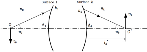
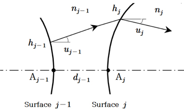
Figure 1 shows a lens system and its marginal ray. Let us begin with the first order properties of the lens system and use the following notations:
• nj, refractive index of the medium after refraction on the j-th surface • hj, incident height of the marginal ray on the j-th surface • uj, paraxial angle of the marginal ray after refraction on the j-th surface • ƞj, image height formed by the j-th surface • rj, curvature radius of the j-th surface • dj, axial distance from the j-th surface to the next surface • refractive power of the j-th surface • converted thickness of dj in the air • αj ≡ njuj, numerical aperture of the marginal ray after refraction • relative height of the marginal ray • transverse magnification of the j-th surface
In Fig. 1, surface 0 is the object, and

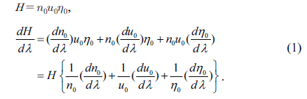
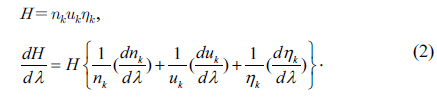
By the same way, Lagrange’s invariant and its chromatic variation in the image-side are given as follows:

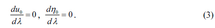
Even though the wavelength of imaging light varies, the object height

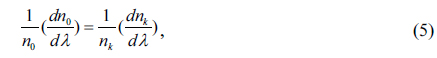
Since Lagrange’s invariant and its chromatic variation should be same on both sides, the chromatic variation of

Consider only the lens system whose object and image are in the same medium,
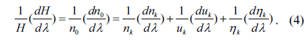
then the chromatic variation of image height is given by Eq. (6):
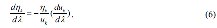
Eq. (6) means that if the chromatic variation of
Let’s return to Fig. 1. The position of paraxial image and its wavelength derivative are given as follows:

Even though a lens system has been stabilized for the chromatic variation of image height, the chromatic variation of
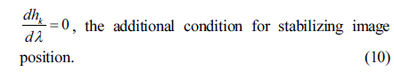
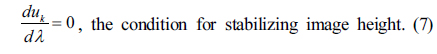
Eqs. (7) and (10) are the stabilizing conditions presented in this paper. In conventional design, chromatic aberrations are corrected to minimize chromatic variation, but we suppress the chromatic variations of the marginal ray in the image-side. By doing so, the image position and the image height are stabilized against chromatic variation at the same time.
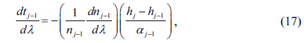
Figure 2 shows a paraxial ray transferring from the (j-1)-th surface to the j-th surface and refracting on the j-th surface. Eq. (11) is the transfer equation of the ray, and Eq. (12) is the refraction equation:


Let’s rewrite Eqs. (11) and (12) by using the converted thickness in the air


From the definitions of

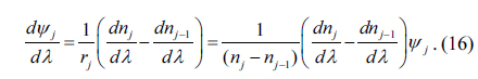
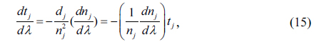
By using Eqs. (13) and (14), the above equations are rewritten as the functions of

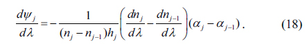
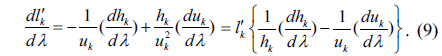
From Eqs. (13), (17), (14) and (18), the chromatic variation of ray height and numerical aperture are given as follows:
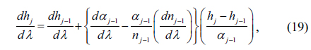
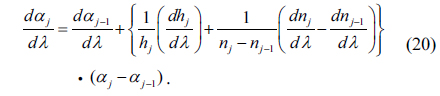
For convenience, let’s rewrite Eqs. (19) and (20) by using the dimensionless design parameter

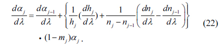
Let’s consider Eqs. (7) and (10), the conditions for stabilizing against chromatic variation. Since the image is in the air and the

III. STABLIZATION OF CEMENTED DOUBLET IN THE AIR
The stabilizing conditions could be applied all of lens system which use two or more kinds of optical materials. But it may not be easy to find the solution of Eqs. (23) and (24) if the lens system is consisted of many elements. However, there is an analytic solution for the case of cemented doublet in the air.
For the case of cemented doublet in the air, the following conditions are always satisfied.
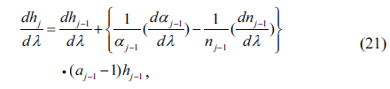
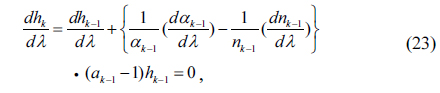
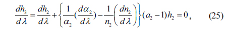
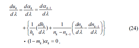
Since the 3rd surface is the last surface of the lens, the stabilizing conditions are given by


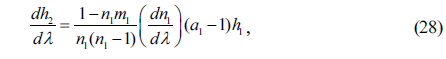
From the recurrence relations of Eqs. (21) and (22), we can get chromatic variations of the marginal ray at the first and the second surfaces:


A cemented doublet has five structural parameters (


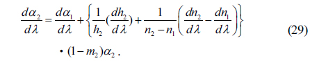
Then, Eq. (29) becomes

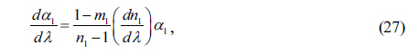
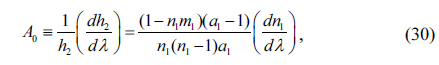
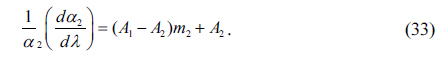
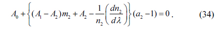
By using Eqs. (33) and (30), we obtain a linear equation of

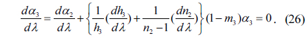
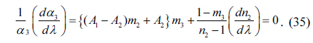
Eq. (34) is the solution of Eq. (25), one of the stabilizing conditions. Let’s consider another condition. Eq. (26) can be rewritten as follows:
Now, Eq. (25) is already satisfied by Eq. (34). By using Eq. (33), the above equation becomes

Since
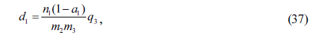
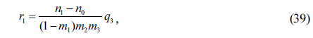
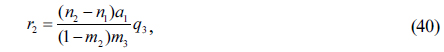
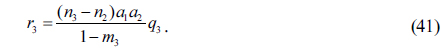
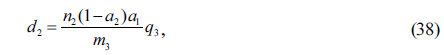
When all of the structural and scaling parameters are determined, design data of the doublet is given as follows:


IV. DESIGN OF A STABLE CEMENTED DOUBLET
Conventional doublets are designed for the entire visible range. But they have relatively poor imaging performance in the blue region around 405 nm wavelength because of rapid change of refractive index. In order to reduce the performance degradation in the blue region, expensive abnormal glasses are used for designing super-achromats [13, 14].
In this study, a stable doublet at 405 nm wavelength is designed by using popular glasses only, not the expensive glasses. Table 1 shows basic specifications of the stable doublet. The glasses and their refractive indices are listed in Table 2. A cemented doublet has five structural parameters and two scaling parameters as mentioned in the previous section. From Tables 1 and 2, some of the design parameters are given as follows:
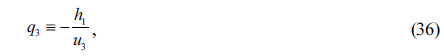
h1 = 12.5 mm , α3 = u3 = -0.01, q3 = n1 = 1.530196 , n2 = 1.650759 , n3 = 1, m1 = 0.
[TABLE 1.] Design specification of the stabilized doublet at wavelength of 405 nm
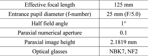
Design specification of the stabilized doublet at wavelength of 405 nm
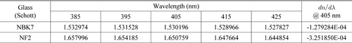
[TABLE 2.] Refractive indices and the first order derivatives

Refractive indices and the first order derivatives
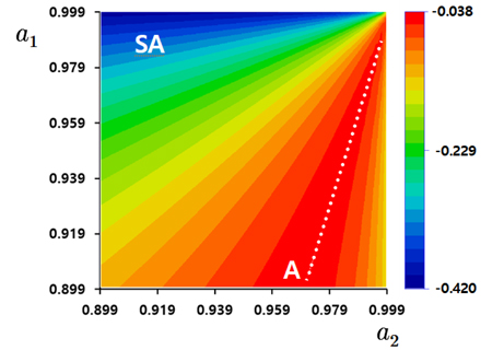
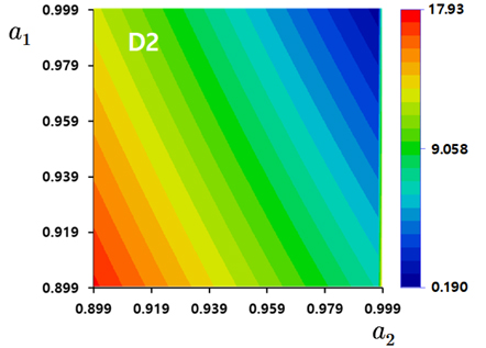
There are four undetermined structural parameters (
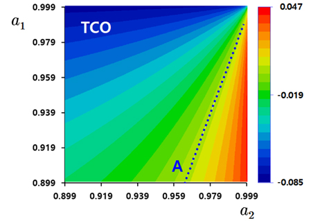
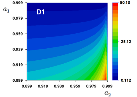
Figure 3 shows the third order spherical aberration (SA) of the stable doublet as a function of (
Considering SA, TCO and axial thicknesses, the stable doublet was taken at
[TABLE 3.] Design data of the stabilized doublet
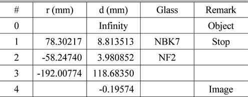
Design data of the stabilized doublet
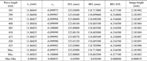
[TABLE 4.] Marginal ray data and its chromatic variations
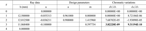
Marginal ray data and its chromatic variations
[TABLE 5.] Chromatic variations of the first order parameters

Chromatic variations of the first order parameters
[TABLE 6.] The third order aberrations of the stabilized doublet (units in mm, calculated by Code V)
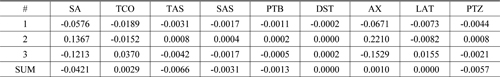
The third order aberrations of the stabilized doublet (units in mm, calculated by Code V)
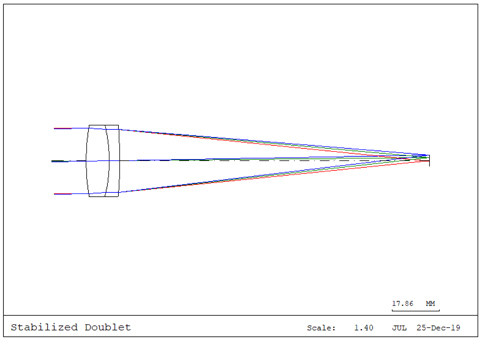
A new design method to obtain a stable lens system against chromatic variation is presented. In the conventional design of a lens system, chromatic aberrations such as axial and lateral color are corrected. In contrast, the new method suppresses chromatic variations of the marginal ray in the image-side. By doing so, the position and the height of image are stabilized against chromatic variation at the same time.
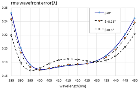
Since the new method is based on paraxial ray tracing, the stabilizing conditions are given by recurrence formulas. However, there is an analytic solution for the case of cemented doublet in the air. By using the analytic solution, a stable cemented doublet at 405 nm wavelength is designed and analyzed. Paraxial properties such as EFL, BFL and image height are very stable as expected. Even though the stable doublet is designed by using popular glasses, the doublet has quite good imaging performance in the blue region. In conclusion, the new design method presented in this paper is expected to be a very useful way to design a stable lens system against chromatic variation at a desired wavelength.