Optical systems characterized by large apertures, long focal lengths and large fields of view (FOVs) are required by the application of high resolution, large spatial and spectral coverage space-to-earth observation. Compared with refractive optical systems, mirror systems are widely utilized in space-borne remote sensing, because of the absence of chromatic aberration, easiness of lightweight design [1], and the compact configuration.
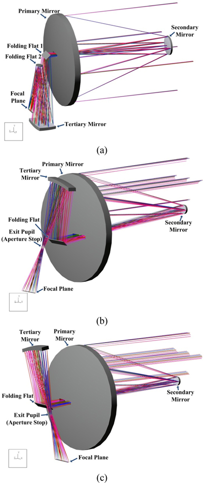
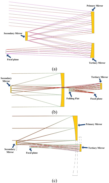
Three-mirror systems are commonly adopted by remote sensors for the advantages of more freedoms in optimization, higher image quality and larger flat focal plane etc. over two-mirror systems. There are mainly three principal categories of three-mirror systems for various applications: the Wetherell type [2, 3] [Fig. 1(a)], the Korsch type [4, 5] (Fig. 1(b)) and the Cook type [6] [Fig. 1(c)]. With an axial pupil which is usually the secondary mirror and an off-axis FOV induced to eliminate the central obstruction, the Wetherell type has the virtues of large FOV, high optical performance, and it easily retains a telecentric final image. However, the absence of the intermediate image and the real exit pupil makes it difficult to control the stray light. Besides, the long distance between the primary and the secondary and the off-axis elements leads to a relatively bulky volume and complicates the manufacture and alignment. The Korsch type features flat field, an advantage of telephoto allowing the system to be folded in a compact envelope [7], an intermediate image where a field mask can be placed to help control the stray light and a real exit pupil. If necessary, a Lyot stop can be set on the exit pupil together with a heat shield, then effective baffling against stray heat is achievable [7, 8]. Considered as the off-axis section of a large parent on-axis Korsch type which is illustrated in Fig. 1(c), the Cook type inherits the features above. Furthermore, due to the off-axis pupil to remove the obstruction, higher-quality image and larger FOV can be achieved by the Cook type than the Korsch one with the same aperture, at the cost of a less-efficient package, a more complex manufacturing and a more demanding alignment. This is because the mirrors are off-axis and the aspheric departure on Cook type is several times higher than that on Korsch type.
In order to perform the detailed and general reconnaissance simultaneously and reduce the cost, we integrate two Cook type optical systems with large f-numbers into a small f-number Korsch type system to synthesize the advantages of the two types. Each system delivers a near diffraction-limited performance. The whole design consists of a concave primary mirror, a convex secondary mirror, three concave tertiary mirrors and is accommodated within a compact package by using four folding flat mirrors. The primary mirror and the secondary mirror are shared by the Korsch type and Cook type optical systems, which means the Cook systems image through the sub-apertures of these two mirrors of the Korsch system. Therefore, in the following text, we call them mutual mirrors.
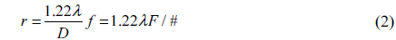
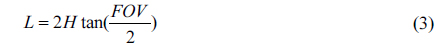
Mathematical relationships between system parameters of remote sensing cameras can be expressed by Eqs. (1)~(3) [9].


where
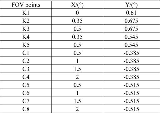
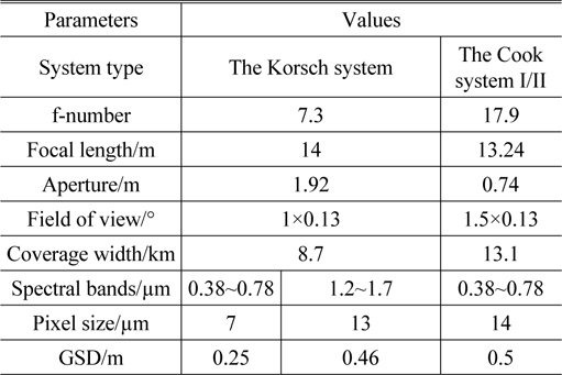
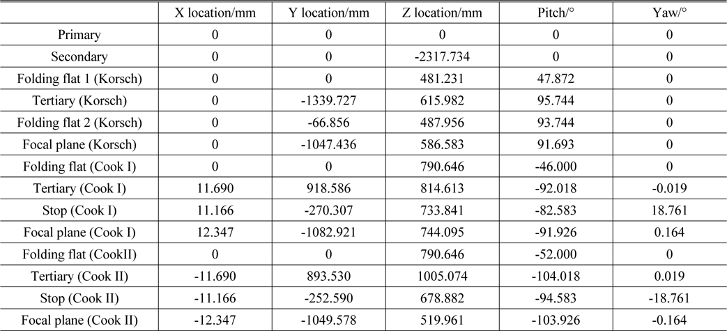
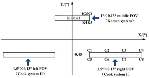
As is plotted in Fig. 2, the whole 4°×0.13° FOV includes three individual parts: the 1°×0.13° middle FOV, the 1.5° ×0.13° right FOV and the 1.5°×0.13° left FOV, imaging through the Korsch system, the Cook system I and the Cook system II respectively. The left and right FOVs are symmetric about the Y axis. The FOV points marked in Fig. 2 are listed in Table 1. The design and optimization of the three individual systems are aiming at their own 0.13° wide FOVs. The technical specifications of the Korsch type and Cook type optical systems are listed in Table 2. Accordingly, the whole coverage width d = 8.7 + 13.1 + 13.1 = 34.9 km. The GSD of the middle 8.7 km coverage is 0.25 m in 0.38 ~ 0.78 μm band, and 0.46 m in 1.2 ~ 1.7 μm band respectively. The GSD of both the lateral 13.1 km coverage is 0.5 m in 0.38 ~ 0.78 μm band. The visible and NIR detectors can be mounted in parallel on the focal plane of the Korsch system for push-broom imaging.
[TABLE 1.] Coordinates of FOV points marked on Fig. 2

Coordinates of FOV points marked on Fig. 2
[TABLE 2.] The technical specifications of the Korsch type and Cook type optical systems

The technical specifications of the Korsch type and Cook type optical systems
The initial structure of the three-mirror optical system is attained by the mathematical derivation which has been presented in a variety of contexts [10-12]. Here, we focus on the optimization procedure of the integrated system.
The primary mirror is selected as the aperture stop of the Korsch system, while the aperture stops of the Cook systems are located at the exit pupils. According to Fig. 2 and Table 1, off-axis FOV of 0.61° along the Y axis is induced into the on-axis Korsch system to avoid the second obstruction caused by the focal plane. The off-axis FOVs along the Y axis of the two off-axis Cook systems are both −0.45°. These biases of FOVs, together with the packaging constraints, prevent the components from vignetting the beam and keep the intermediate images and the real exit pupils of different systems available.
The primary mirror and secondary mirror are conics. The three tertiary mirrors are aspheres with 6th order coefficient. The asphere surface sag is as follows:
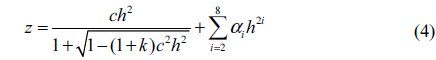
Where
The optical axis, namely the common axis of the primary and secondary mirrors are parallel to the Z axis. Since the primary mirror and secondary mirror are mutual, during optimization, special attention is needed to limit the apertures of these two mirrors in Cook systems inside the effective apertures of the corresponding mirrors in the Korsch system. The parameters of the primary mirrors in different systems must be kept the same as they are varying, and so is the secondary mirror.
Driven by the character of the FOV, the two Cook systems are almost symmetric about the Y-Z plane, except for the tilts of the folding flats which are set differently deliberately to spatially separate the exit pupils. In other words, the location and the orientation of the two tertiary mirrors of the Cook systems are symmetric about the Y-Z plane when the folding mirrors are removed. Therefore, only one Cook system needs to be optimized, and then the parameters of the other one are set according to the result. The tilts and decenters of the tertiary mirrors in the Cook system are set as variables to further balance the aberrations of the off-axis FOVs, except for the curvatures, conic constants, aspheric coefficients and spaces.
Other considerations should be taken into account to (1) control the distance between the primary and the secondary mirrors; (2) restrict the obstruction area of the secondary mirror; (3) make allowance for the mechanical structures such as the stops and baffles.
IV. CONFIGURATION OF OPTICAL SYSTEM
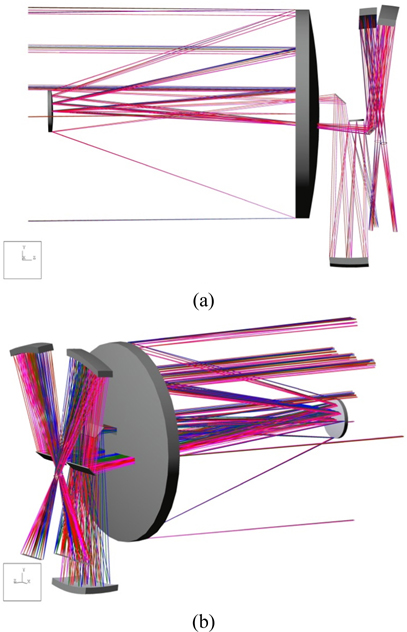
The optical configurations of the Korsch system, the Cook system I, the Cook system II are demonstrated in Fig. 3 (a), (b) and (c). And the whole system is illustrated in Fig. 4 (a) and (b). Table 3 lists the parameters of the powered surface after optimization. Table 4 lists the locations of the optical components, namely the local surface coordinates with respect to the vertex point of the primary mirror. The reference point of every mirror is its own vertex point.
[TABLE 3.] Parameters of the powered surfaces
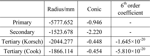
Parameters of the powered surfaces
[TABLE 4.] Locations of the optical components

Locations of the optical components
Suppose the folding mirrors are removed and the position and the orientation of the tertiary mirrors are adjusted accordingly. Then, their decenters and tilts are listed in Table 5. Obviously, tertiary mirror of the Korsch system is on the common axis of the primary and secondary, while the tertiary mirrors of the two Cook systems are not, but are symmetric about the Y-Z plane.
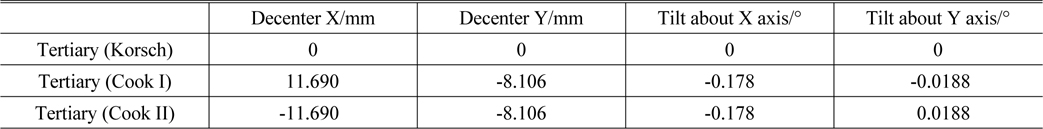
Decenters and tilts of tertiary mirrors after removing the folding mirrors and adjusting the positions and the orientations accordingly
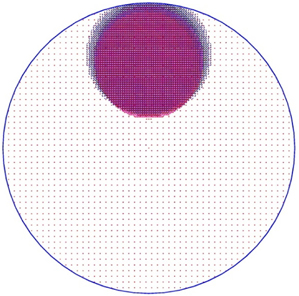
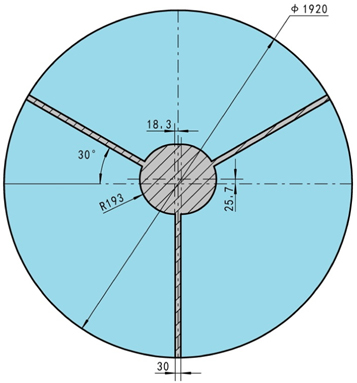
The ray footprints of the mutual primary mirror are presented in Fig. 5. It’s obvious that the footprints of the two Cook systems are within the envelope of the Korsch system and the primary mirror is axisymmetric, which reduces the difficulty of fabrication and test significantly compared to the off-axis equivalent. Here, we ignore the influence of the obstruction which will be discussed in the next chapter.
It’s spatially adequate to install the field stops and the Lyot stops at the intermediate images and the real exit pupils respectively for stray radiation control. Together with the main baffle, the secondary mirror baffle, the primary central baffles and light shields, the stray light can be mitigated effectively. The folding flat 2 (Fig. 3 (a)) is located at the exit pupil of the Korsch system. There are enough room behind it for other subsystems to further improve the performance functionally if appropriate adjustments are made: (1) modify the folding flat 2 into a deformable mirror to compensate for the figure error of the primary and the system wavefront error [13, 14], (2) replace the flat mirror with a splitter and design a lens working in a different waveband to match the pupil and to widen the spectral range of the system. A compact package of
With almost the same size of a traditional Korsch system, the integrated system described above can accomplish high resolution and wide field (about 4 times of the traditional one) remote sensing simultaneously, only at the cost of two more tertiary mirrors. The parameters of the two tertiary mirrors in the Cook systems are identical to each other. Besides, the primary and secondary mirrors of the on-axis Korsch system are shared with the Cook systems. Therefore, compared to three individual three-mirror optical systems, the fabrication and test are simplified dramatically. And the symmetry of the on-axis optical elements makes the system less sensitive to misalignments.
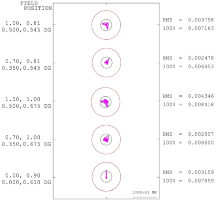
Since the FOV is symmetric about the Y-Z plane, as illustrated in Fig. 2 and Table 1, five and eight representative field points of the Korsch system and Cook system are selected respectively to evaluate the image quality.
When the pupil is obscured, the shape and size of the diffraction-limited point spread function (PSF) are influenced by the obscuration ratio. If the obstruction is centrally symmetric, the increase of the obscuration ratio leads to the reduction of the first maximum and the enhancement of the second maximum, thus decreases and reshapes the Modulation Transfer Function (MTF) curves [15]. Here, we ignore the effect of the secondary baffle, as is shown in Fig. 6. the obstruction of the Korsch system caused by the spiders and the secondary mirror is not circular symmetry. The shape of PSF and the MTF in different directions will change correspondingly. The quality evaluation is performed taking into account the obstruction. The Cook systems are unobscured according to Fig. 4(a).
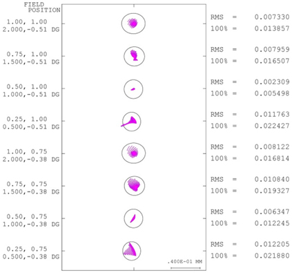
The spot diagram of the Korsch system is shown in Fig. 7. According to Eq. (2), the radiuses of Airy disks in visible (black circle) and NIR (red circle) spectrum ranges are 5.16 μm and 12.9 μm. Fig. 8 illustrates the spot diagram of the Cook system, and the radius of the Airy disk in visible band is 12.7 μm. The root mean square (rms) spot diameters all over the field are less than the Airy disks in different bands, and are within two pixels.
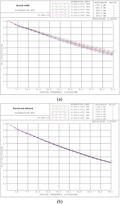
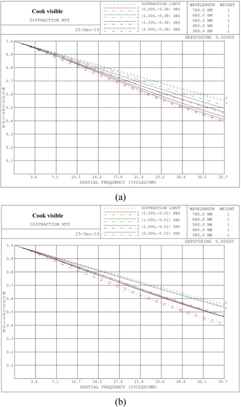
The MTF curves for visible and NIR bands of Korsch system are shown in Fig. 9(a) and (b). Figs. 10(a) and (b) are for the Cook system. Over the respective FOVs, the MTF values of the Korsch system are above 0.474 and 0.412 in visible and NIR bands, and the MTF of the Cook system is above 0.392 at the corresponding Nyquist frequencies (71.4 lp/mm, 38.5 lp/mm and 35.7 lp/mm).
We have presented the optical design which integrates an f/7.3 Korsch with two f/17.9 Cook systems. The system consists of a mutual concave primary mirror, a mutual convex secondary mirror, three concave tertiary mirrors and four flat mirrors which fold the optical path into a compact envelope. The optimization strategy, feasibility of manufacture and alignment are analyzed. At the altitude of 500 km, the GSD of 0.25 m in visible range (0.38 ~ 0.78 μm) and 0.46 m in NIR band (1.2 ~ 1.7 μm) over a FOV of 1×0.13° can be attained through the Korsch system with a focal length of 14 m, the GSD of 0.5 m in visible range over two lateral FOVs of 1.5×0.13° can be attained through the two Cook systems whose focal lengths are both 13.24 m. The whole strip FOV is 4×0.13°, which covers an area of 34.9 km×1.1 km on the earth. The intermediate images and the real exit pupils in the whole system are all available for stray light suppressing. Near diffraction-limited image quality is achieved all over the FOV and the spectrum ranges. The ability of high resolution, large field of view and multi-spectral imaging make it a promising candidate for a remote sensing optical system.