The primary water stress corrosion cracking (PWSCC) of Alloy 600 in a pressurized water reactor (PWR) has been reported in the control rod drive mechanism (CRDM), pressurizer instrumentation, and the pressurizer heater[1-4]. In the original PWRs, PWSCC was not appropriately considered. Beginning in the mid-seventies, the PWR plants suffered from a sequence of PWSCC events which were mostly confined to S/G tubes, initially ODSCC then PWSCC. In forged Alloy 600 materials, PWSCC was first reported in the Bugey 3 vessel head penetration in September 1991. All reactor vessel heads (RVH) with Alloy 600 penetrations (54 RVH out of 58) were replaced in France. Other PWRs experienced cracking, which was attributed to the PWSCC of the major primary side welds made from Alloy 182 at the end of the year 2000. The three events concerned had dissimilar metal butt welds between the main austenitic stainless steel primary circuit piping and the outlet pressure vessel nozzles of Ringhals 4 and V. C. Summer and some J-groove welds of the CRDM of the RVH at Oconee 1 [4].
In addition to the RVH, PWSCC of Alloy 182/82 has been reported at bottom mounted instrumentation (BMI) nozzle J-welds, steam generator (SG) drain J-welds, drain nozzles and SG tube sheet cladding. Since 2006, 344 PWSCC incidents of Alloy 600/82/182 were reported in RVH, SG, Pressurizer, and other primary side piping. Recently, two cases of boric acid precipitation due to PWSCC were reported on the bottom head surface of SG in Korea [5].
The PWSCC resistance of Ni base alloys with intergranular carbide morphologies is higher than those with intragranular ones in low oxygen primary water of PWR [6]. On the other hand, in acidic oxidized solutions like sodium sulfate or sodium tetrathionate solutions (Na2S4O6), the Ni base alloys with a lot of carbides at the grain boundaries show less SCC resistance [7-9]. Thus grain boundary carbides or Cr depletion of the Ni base alloys behave differently on the SCC in each condition. The objective of the paper is to show a different role of the grain boundary carbides on the SCC in oxidized acidic solution and simulated PWR primary water and to review the increase of PWSCC resistance mechanism of Ni base alloys.
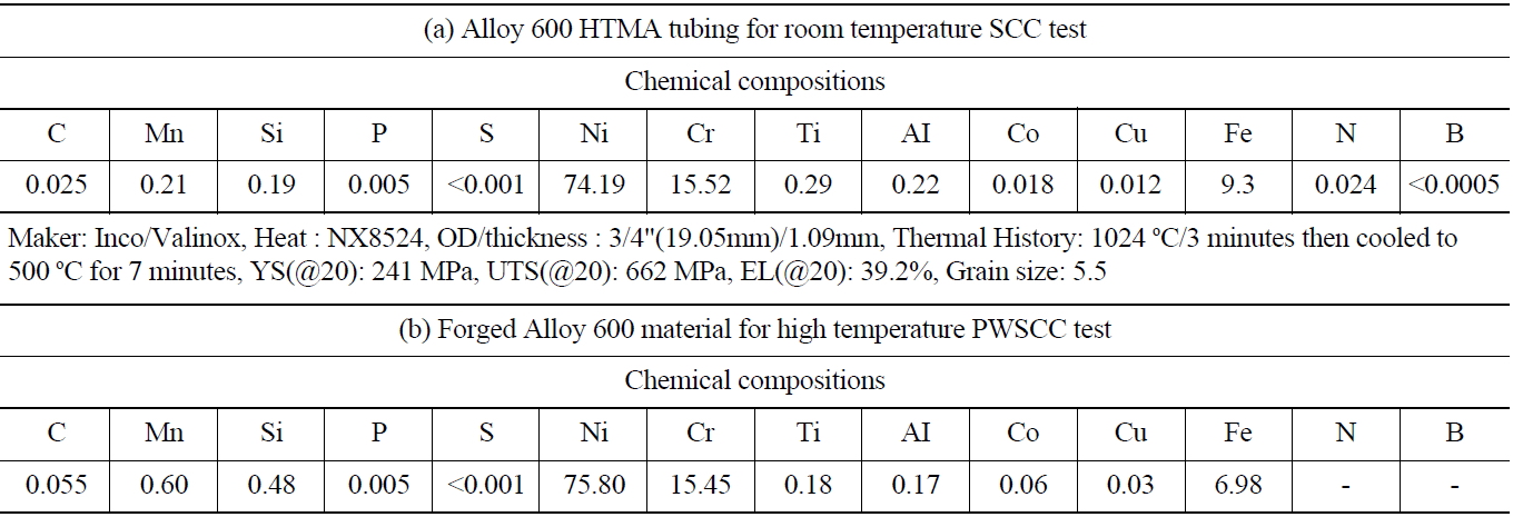
High temperature mill-annealed (HTMA) Alloy 600 SG tubing was used for this investigation. The thickness and outside diameter of the specimen was 1.09 mm and 19.05 mm, respectively. The HTMA for as-received tubing was at 1060~1070 ℃, which is a high enough temperature to ensure that most carbon in the alloy is dissolved and that no carbide precipitates remain. Table 1 shows information of the test material.
[Table 1.] Information of the Test Material Alloy 600 Tubing and Forged Alloy 600

Information of the Test Material Alloy 600 Tubing and Forged Alloy 600
For PWSCC test, forged Alloy 600 material was used. The original dimension of the material was 120 mm in diameter, 130 mm in length, respectively. The hot formed material was heat treated for 3 hours at 950 ℃ then water cooled.
2.2 SCC Test in Acidic Solution
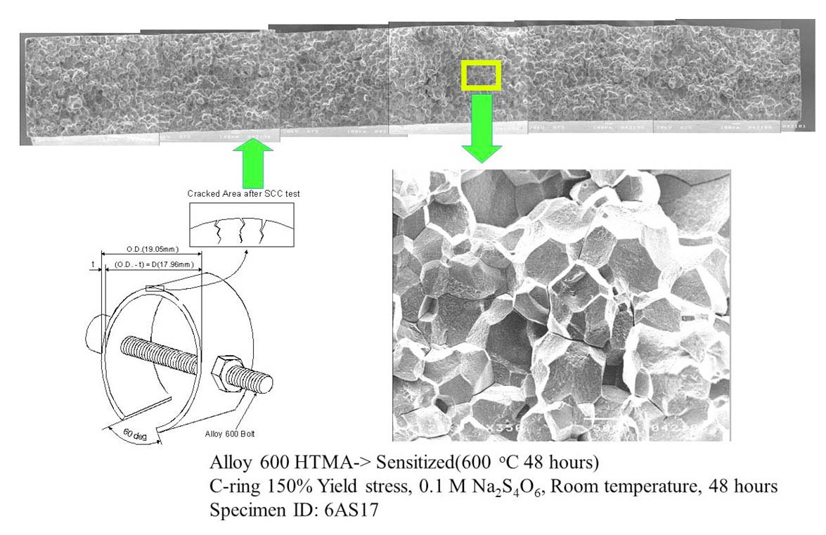
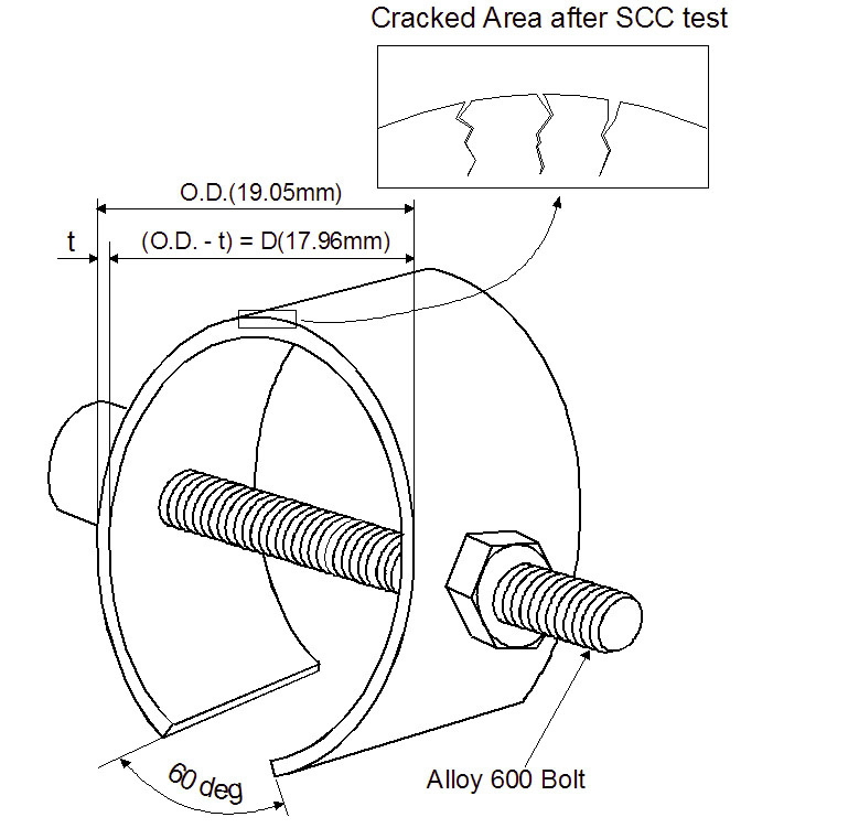
The as-received tubing was heat treated at 600 ℃ for 48 hours in a vacuum to sensitize the material for easier cracking in the test solution (Na2S4O6) at room temperature. The C-ring specimens were prepared according to the ASTM G38 [10]. They strained to a constant deflection in the range of plastic deformation using Alloy 600 bolts and nuts, as shown schematically in Fig. 1. The apex of the specimens was ground with # 1000 emery paper before the deflection. The relationship between elastic stress at the apex and the variation of tube diameter is described as follows [10].
ODf = OD - Δ ……………. Eq.(1)
Δ = fπD2/4EtZ
where,
OD : Outside diameter before stressing
ODf : Outside diameter of stressed C-ring
Δ : Change of OD giving desired stress
f : Applied stress
D : Mean diameter (OD-t)
t : Wall thickness
E : Modulus of elasticity
Z : Correction factor for curved beams
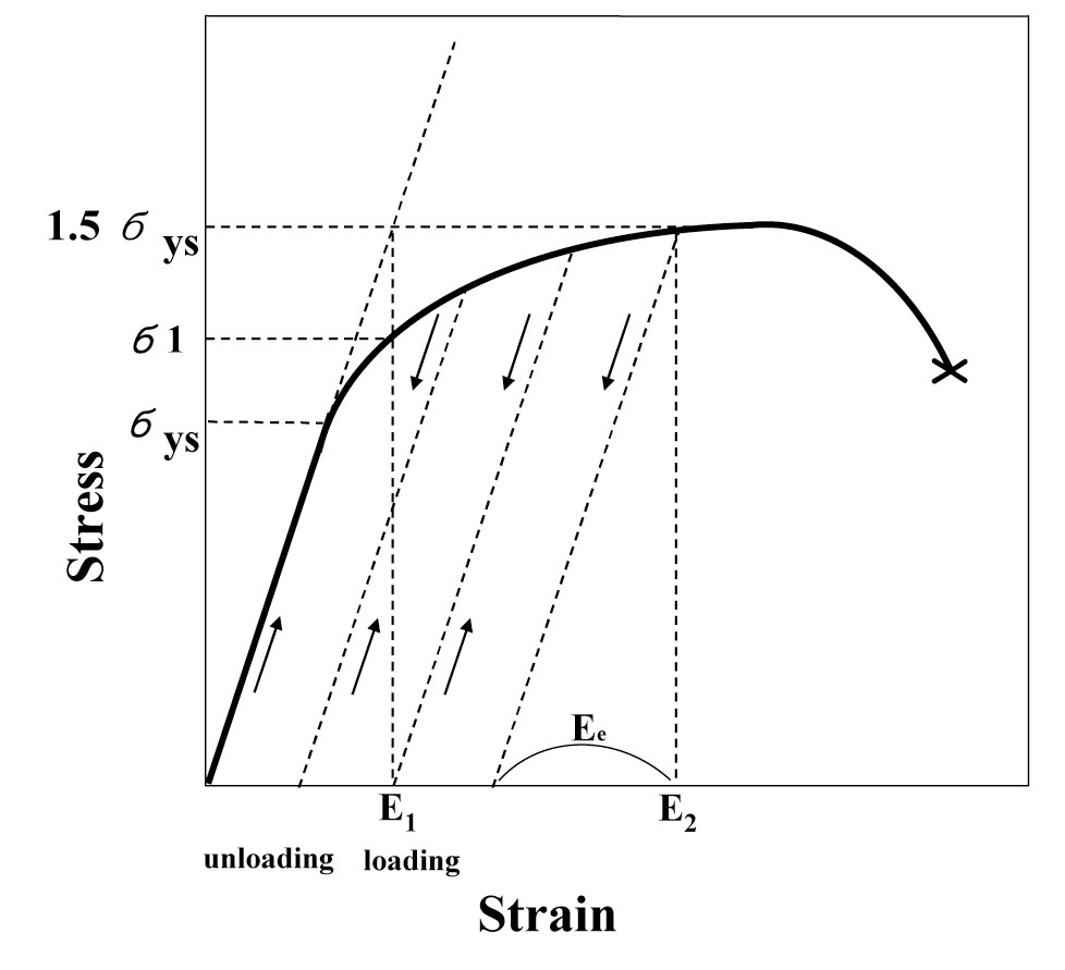
If one considers only the Hooke’s law and Eq (1), it would not be possible to apply over 100% of yield stress on the C-ring apex. However, it is possible to load the Cring sample until the elastic strain reaches at Ee as shown in Fig. 2.
In these experiments, the stress was applied on the C-rings by repeating the process of loading, unloading, and reloading to increase an elastic portion of deformation at room temperature. It was then possible to apply a stress above 100% of yield stress according to the Eq. (1). The applied stress on the C-ring test specimens was 90%, 100%, 125%, and 150% of the room temperature yield stress of the material.
The stress loaded C-ring specimens were cleaned with acetone and distilled water. The specimens were then exposed to 0.01 M or 0.1 M of Na2S4O6 test solution at room temperature for up to 72 hours. The apex of test specimens was examined with a low magnification stereo microscope during the exposure at 6 hour intervals to determine crack initiation time.
2.3 SCC Test in Simulated PWR Primary Solution
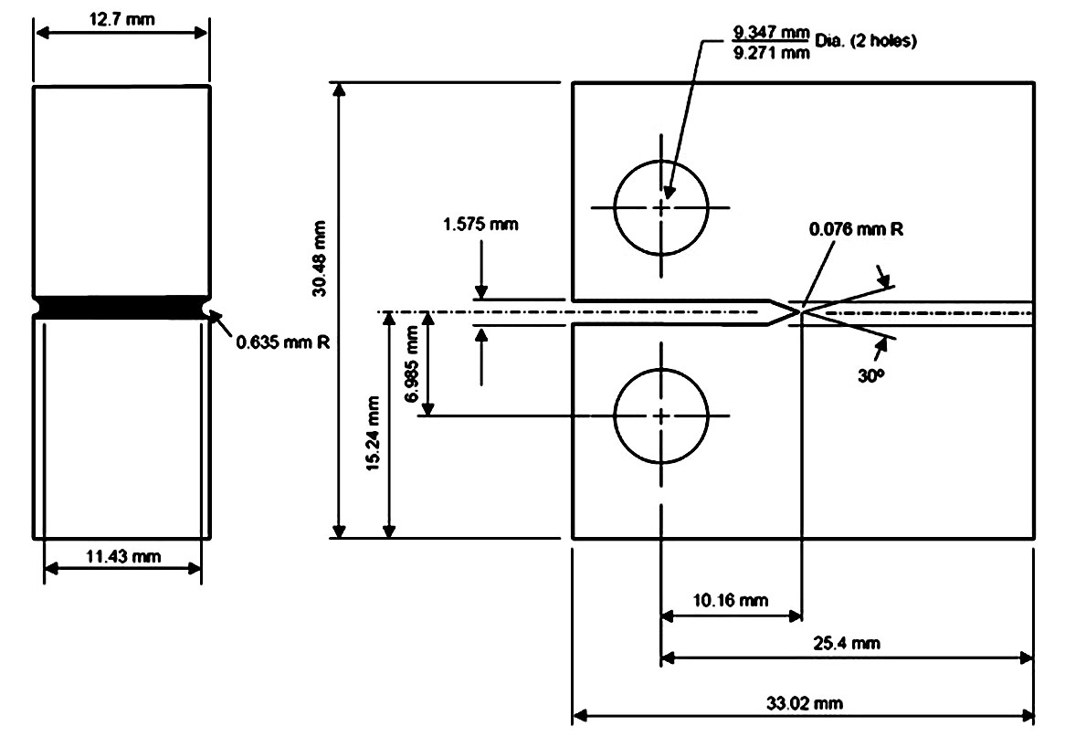
In the present PWSCC experiment, 1/2 compact tension (CT) specimens were used and its dimensions are shown in Figure 3.
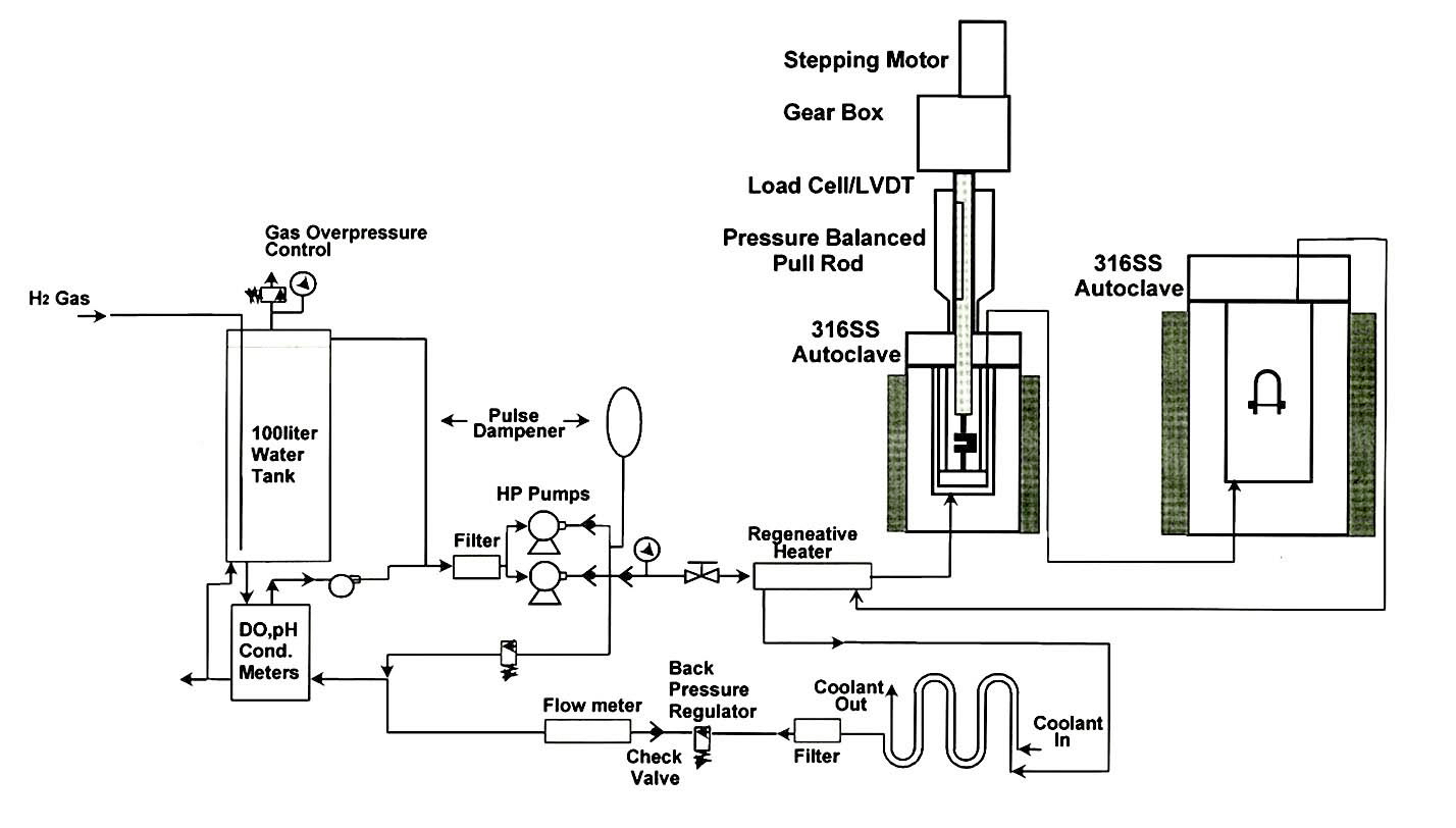
Before the PWSCC test, the CT specimen was fatigue pre-cracked to a length of about 2 mm in air. The PWSCC test was conducted under the simulated primary water environmental conditions of 1200 ppm of B and 2 ppm of Li under internal pressure of 2300 psi(or 15.9 MPa) at 340 ℃. Dissolved oxygen(DO) content and hydrogen partial pressure of the water was below 5 ppb and 14.3 psi (or 0.1 MPa), respectively. The maximum stress intensity factor at a crack tip was maintained at 30 MPa√ m. Major experimental parameters such as the temperature, load, displacement, pH, electric conductivity, ECP and DO were being monitored and collected by PC through an A/D converter. A direct current of 5 A was applied to the CT specimen, and the current was periodically reversed via a programmed current source. Voltage drops were measured from the CT specimen and a reference coupon through digital voltmeters. The crack length was then calculated using the Hicks and Pichard (H&P) equation on the basis of the measured voltages [11,12]. The reference coupon prepared with the same material as the CT specimen was equipped to calibrate the material’s resistivity changes occurring after long term exposure at high test temperature. A schematic diagram of the test loop is shown in Figure 4.
3.1 Carbide Precipitation and SCC Susceptibility
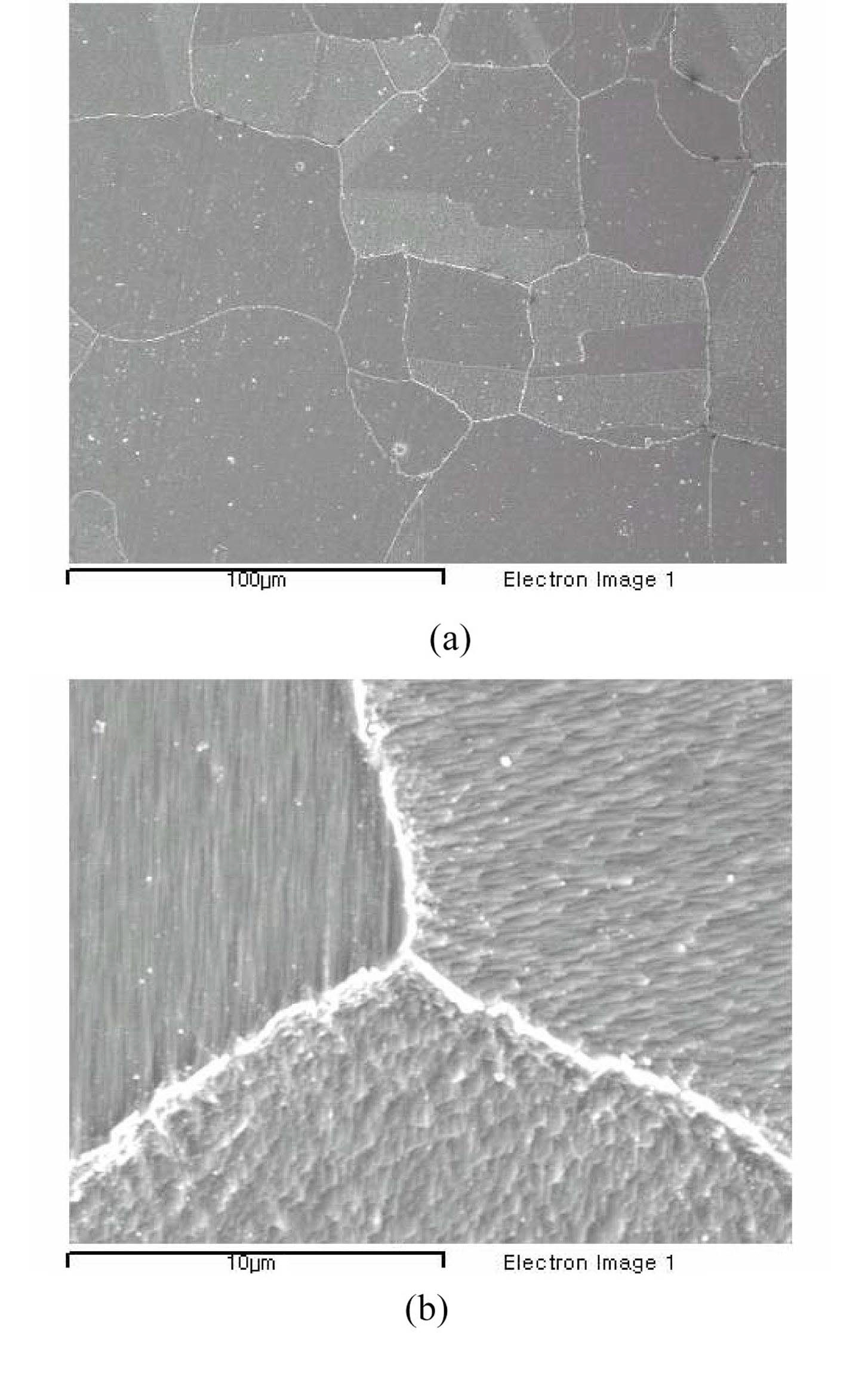
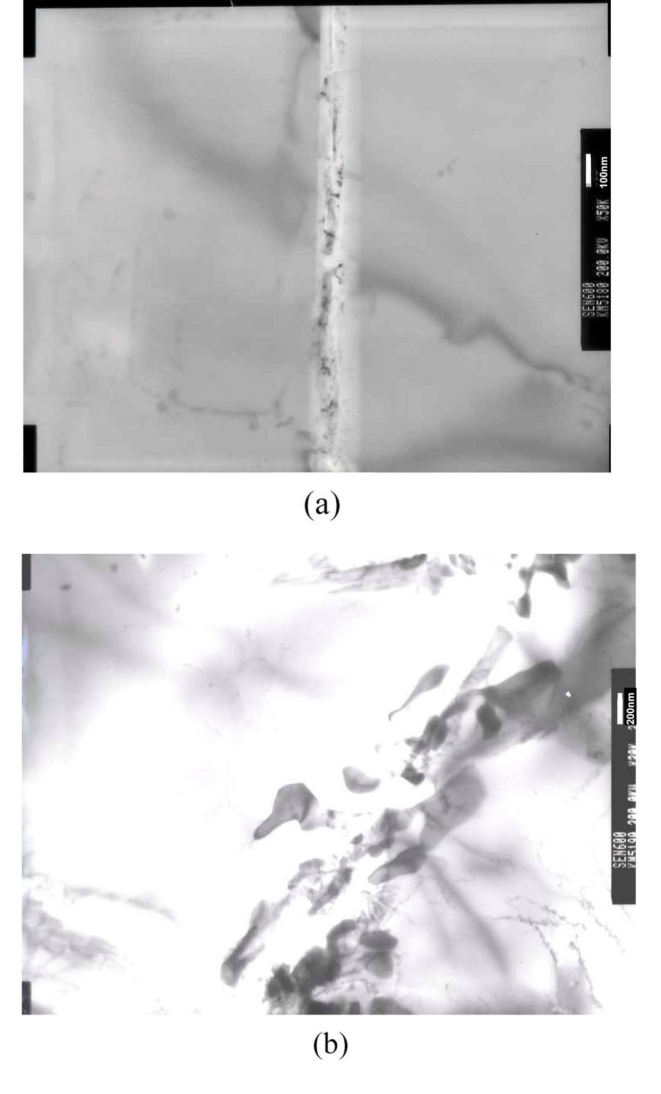
Figure 5 is of scanning electron micrographs (SEM) of the sensitized testing material. The average grain size is about 50 to 100 μm and the carbides are well grown up as shown in the micrographs. Figure 6 is of transmission electron micrographs (TEM) of the material showing clear formation of carbides and their morphology on the grain boundaries. It is evident that the samples are fully sensitized by the heat treatment.
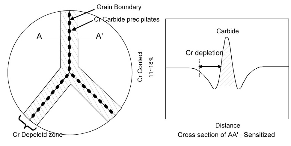
Sensitization of stainless steel (SS) is caused by the precipitation of chromium carbides along the grain boundaries. This precipitation depletes the Cr content near the grain boundaries, thereby decreasing its corrosion resistance. The Cr depletion near grain boundaries of sensitized Type 304 SS is schematically shown in Figure 7. In the case of austenitic stainless, chromium carbides and a chromium depleted zone form at a maximum rate of around 815 ℃, and the rate decreases slowly at lower temperatures down to 482 ℃. The sensitization rate is a complex function of a number of factors. For austenitic stainless steels, the sensitization is prevented by keeping the carbon content of the alloy below 0.03% e.g., Type 304L, 316L. In ferric stainless steels, the formation of chromium depleted zone is only suppressed by combining all carbon and nitrogen in the alloy with titanium or niobium.
The austenitic stainless steels can be quenched above 871 ℃ to prevent precipitation, but ferritic stainless steels cannot be quenched rapidly enough.
In the mid-seventies, intergranular stress corrosion cracking (IGSCC) problems occurred in the heat-affected zones of Type 304 stainless steel welded piping which were used in BWRs. One of the main causes of SCC was the presence of chromium carbide precipitates and chromium depletion at the grain boundaries of the austenitic stainless steel, i.e., sensitization.
Ni base alloys also show chromium depletion along the grain boundaries when they are exposed to certain high temperatures and slowly cooled to room temperature, depending on the carbon content of the materials. These
sensitized Ni base alloys exhibit high intergranular corrosion rates in oxidized acidic solutions at room or high temperatures (for example, Na2S4O6 solutions)[7].
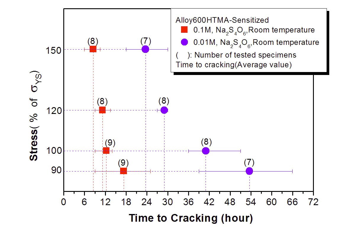
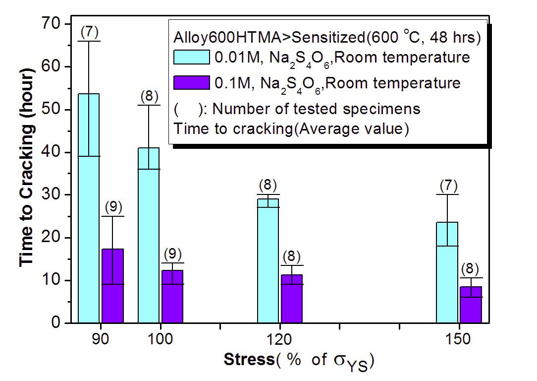
Figures 8 and 9 show the results of our C-ring tests for the sensitized HTMA Alloy 600 in 0.1 and 0.01M Na2S4O6 solutions at room temperature. Cracking susceptibility is plotted in terms of the applied stress and time of cracking. A cracking time as short as 7 hours was observed for the specimen loaded at 150% of the yield stress. The cracking
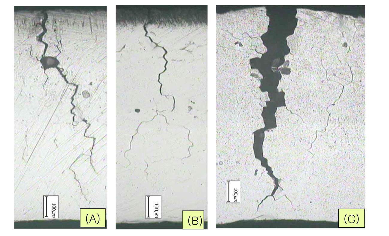
time here means time to observe a crack first on the specimen apex by a low magnification microscope at every 6 hour interval to determine crack initiation time. Figure 10 shows a cross section of cracked C-ring specimens tested in 0.1 M sodium tetrathionate solution. The typical cracking mode of the sensitized Alloy 600 is intergranular as shown in Figure 11. These results clearly show that the sensitized microstructure of Alloy 600 is very susceptible to SCC in the oxidized acidic solution, which is a similar behavior to the cracking of sensitized SS.
Some researchers pointed out that grain boundary carbide and chromium depletion areas
formed in the sensitized alloy 600 accelerate the SCC initiation and propagate under the acidic condition. One of the explanations considered is that enriched nickel in the chromium depletion zone is easy to dissolve in an acidic solution[13]. So, the corrosion resistance of grain boundary with chromium depletion zone is low in the acidic solution.
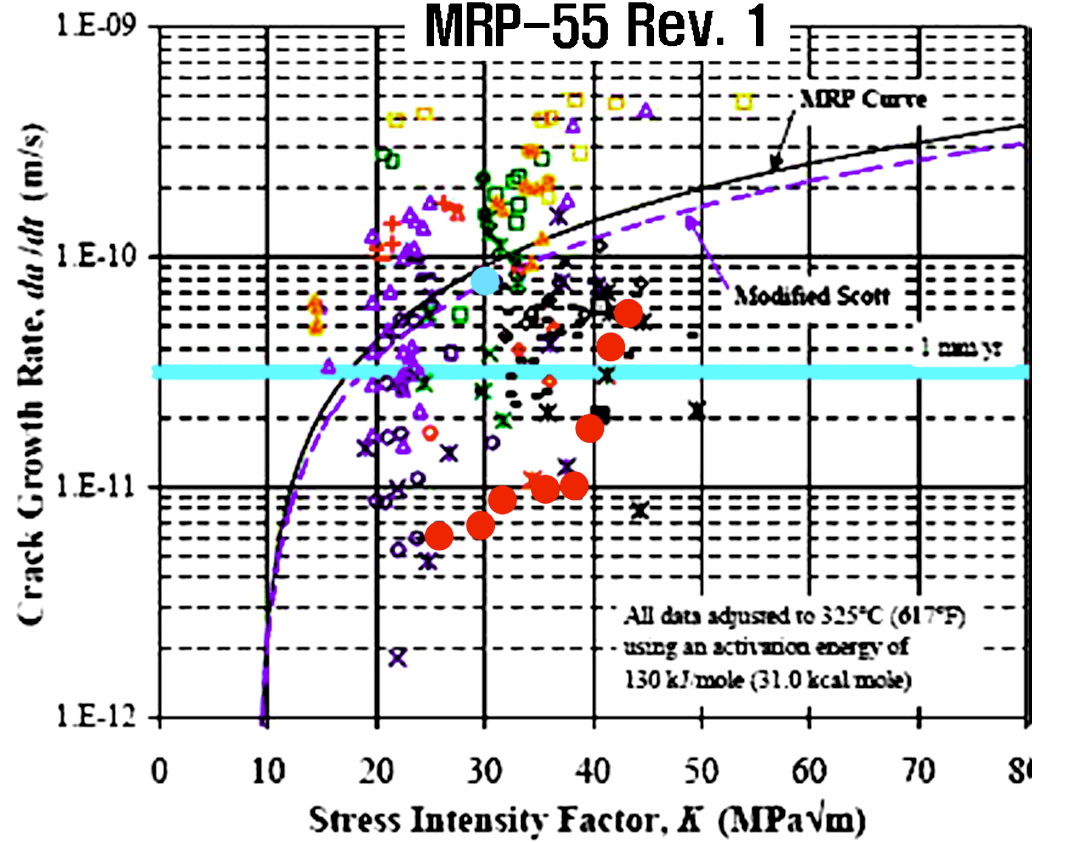
PWSCC resistance of the two Alloy 600 obtained in this work is plotted in Figure 12. It is believed that the main
reason for the different crack growth rate (CGR) of the two alloys is from micro structural differences, especially from the differences in the grain boundary carbide morphologies of the materials.
Thermal treatments which produce chromium carbide at grain boundaries provide better resistance to SCC in high purity water, as reported by Coriou in 1973 [14]. It is generally considered that Alloy 600 with many carbides on the grain boundary were found to be more resistant to PWSCC, whereas those with many intragranular carbides are the most susceptible [15-17].
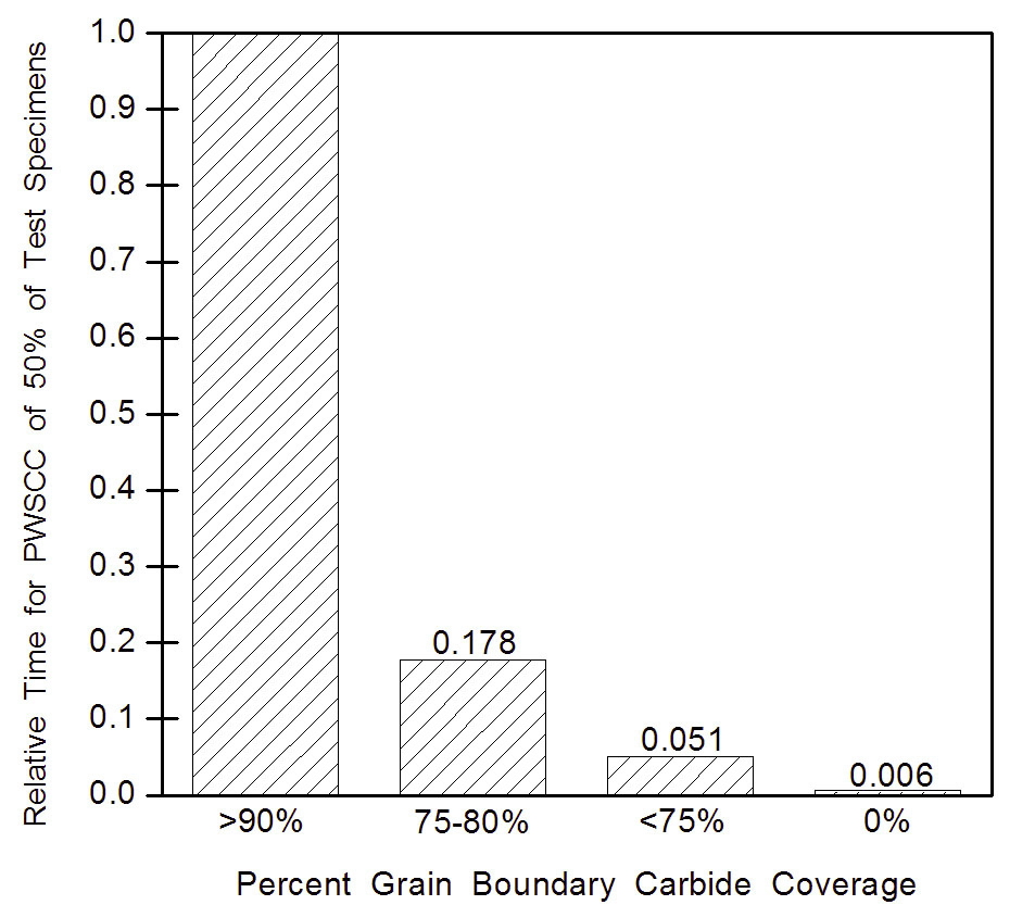
Figure 13 illustrates the susceptibility to the PWSCC of Ni base alloys in primary water, in terms of grain boundary carbide coverage[3]. The best resistance to the PWSCC of Alloy 600 in primary water appears to be associated with the chromium carbide decorated microstructure at the grain boundaries.
3.2 Fabrication Variables and SCC Susceptibility
The main fabrication variables which control the carbide morphology in Alloy 600 are the final forming process and annealing conditions. These factors significantly affect PWSCC susceptibility of the materials [4].
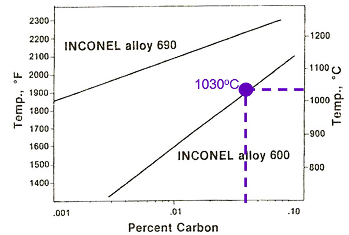
Presence of Cr carbides within grains and at grain boundaries is influenced by the prior and the final forming, heating and annealing processes. The material is cold worked during final forming operations and then recrystallized during the final annealing treatment with cooling resulting in new grain boundaries. The solubility of the carbides during annealing is a strong function of the annealing temperature. At a low annealing temperature, carbides do not fully go into the base alloy so large amounts of carbides remain within the former grains after cooling and there are few grain boundary carbides. For example, carbides in a material with 0.04 % of carbon content can be fully solutionized at 1030 ℃ based on the carbon solubility as seen in Fig. 14[18].
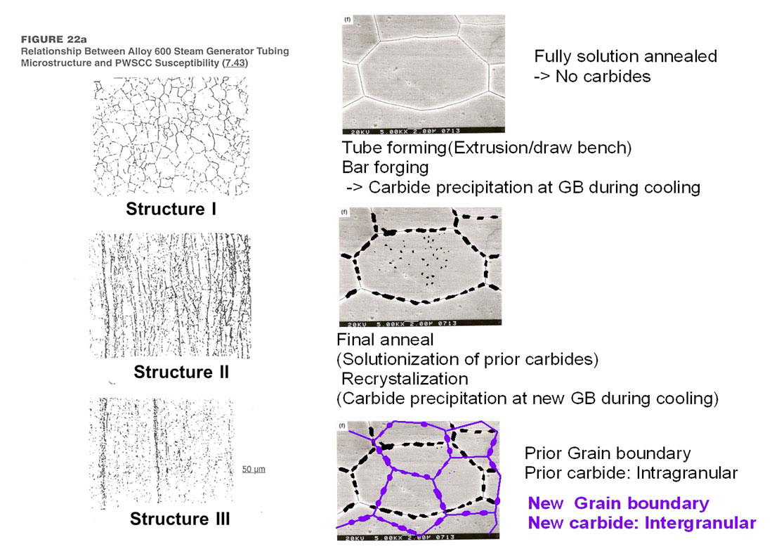
Figure 15 shows different microstructures depending on the fabrication history of Ni base alloys[19]. The material with a final annealing at high temperature shows intergranular carbides, whereas the one with a final annealing at a low temperature shows intragranular carbides.
At a high annealing temperature, carbides dissolve almost completely into the solution and the grains grow in size which reduces the grain boundary surface area, and carbides precipitate at the new grain boundaries when it cools down. Therefore, a high temperature annealing results in large grains, copious grain boundary (intergranular) carbides, and few intragranular carbides.
3.3 Beneficial Effect of Intergranular Carbides on PWSCC Resistance
The occurrence of PWSCC of Alloy 600 strongly depends on the presence of intergranular carbides. Intergranular carbides are formed by mill-annealing at high temperatures (e.g., 1065 ℃) during the final 15 hour heat and thermal treatment at 705 ℃ . This heat treatment makes Alloy 600 tubes resistant to PWSCC. On the other hand, low millannealing temperatures produce intragranular carbides, which make tubes susceptible to PWSCC.
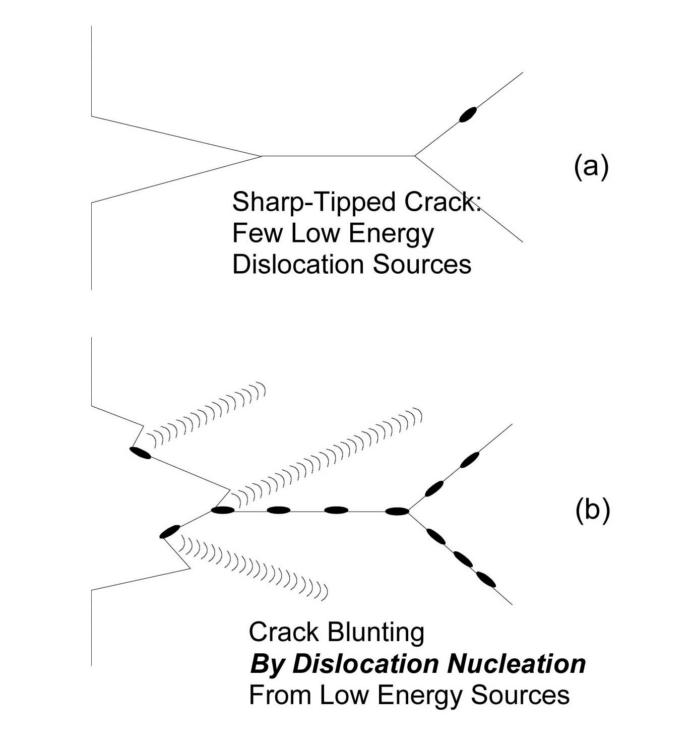
Bruemmer proposed a model to explain the role of intergranular carbides [6]. Grain boundary carbides promoted crack blunting due to their effectiveness as dislocation sources, as illustrated in Fig. 16. Hwang et. al. also have showed different dislocation behaviors from grain boundary with and without grain boundary carbide structures[20,21]. As reported by Bruemmer [6], the larger the dislocations in alloy, the greater the number of carbides at the grain boundaries, the more dislocation sources will be present to blunt the crack. Smialowska and Rebak proposed another possible explanation that Alloy 600 material passivates more readily under the presence of grain boundary carbides [22,23].
Undissolved carbon in materials with high carbon content hinders grain growth during heat treatments, so a small grain sized microstructure is developed. The small grain alloys shows high yield strength which results in a susceptible microstructure. Likewise, low temperature annealing causes an intragranular carbide structure which is susceptible to PWSCC.
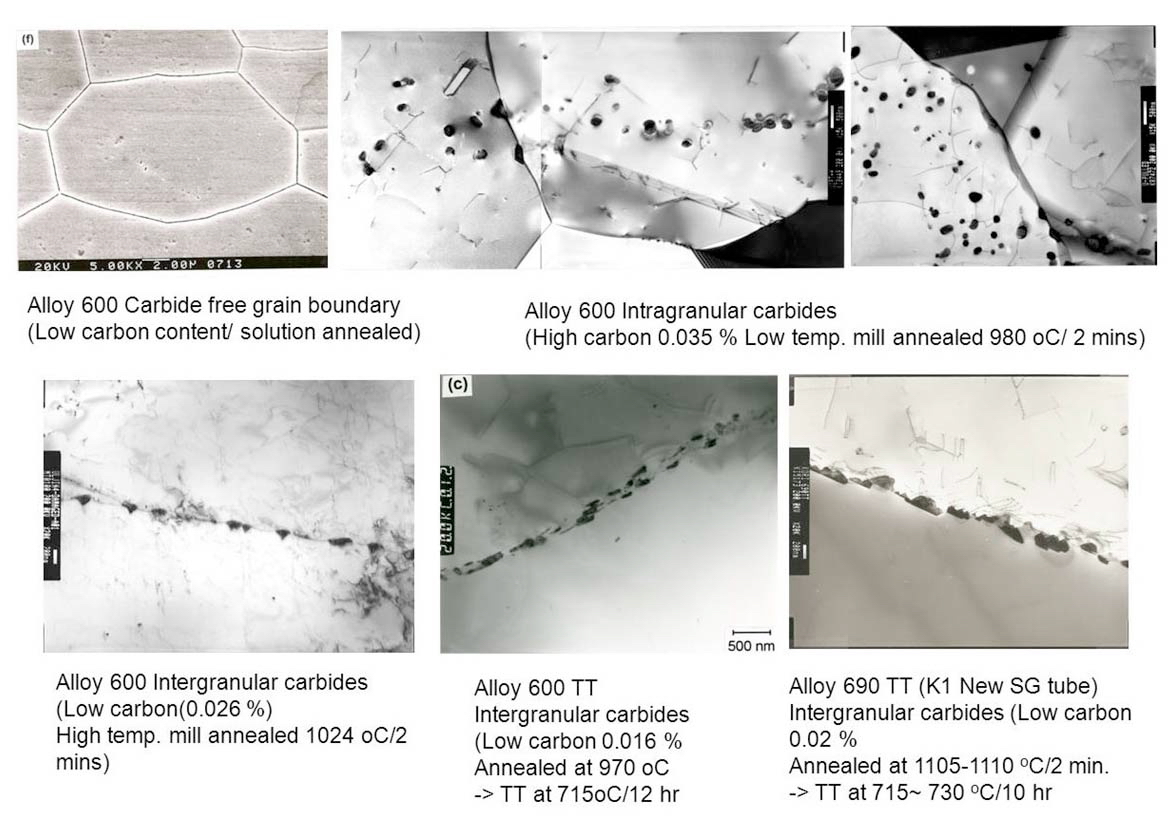
Figure 17 shows a comparison of different microstructures which have a different carbon content or a different thermal history. The typical examples of the different microstructures shown in Fig. 17 are categorized as below:
- Less grain boundary carbides due to a low carbon content or solution annealing.
- Intragranular carbides with high carbon, e.g., a low temperature mill annealed structure at 980 ℃ for 2 minutes of 0.035 % of carbon. (LTMA Alloy 600)
- Intergranular carbides with low carbon (0.026 %), a high temperature mill-annealing at 1024 ℃ for 2 minutes.(HTMA alloy 600)
- Intergranular carbides with low carbon (0.016 %), annealed at 970 ℃, then thermally treated at 715 ℃ for 12 hours (Thermally treated Alloy 600)
- Intergranular carbides with low carbon (0.02 %), annealed at 1105-1110 ℃ for 2 minutes, then thermally treated at 715~ 730 ℃ for 10 hours. (Thermally treated Alloy 690).
The role of grain boundary carbides in the SCC behavior of Ni base alloys was investigated.
(a) Sensitized Ni base alloys exhibit a high intergranular corrosion rate in oxidized acidic solution. The sensitized Alloy 600 showed a similar SCC behavior of sensitized SS in the oxidized acidic solution.
(b) PWSCC resistance of Alloy 600 in primary water environment appears to be associated with the Cr carbide decorated microstructure at grain boundaries.
(c) Grain boundary carbides promote crack blunting due to their effectiveness as a dislocation source. The greater the number of carbides at the grain boundaries, the more dislocation sources are present to blunt the crack.


![PWSCC Susceptibility vs. Grain Boundary Carbide Coverage[4].](http://oak.go.kr/repository/journal/12581/OJRHBJ_2013_v45n1_73_f013.jpg)
![Annealing Temperature and Carbon Contents in Alloy 600 and 690[18].](http://oak.go.kr/repository/journal/12581/OJRHBJ_2013_v45n1_73_f014.jpg)
![Different Microstructure Depending on Fabrication History of Ni Base Alloys[19].](http://oak.go.kr/repository/journal/12581/OJRHBJ_2013_v45n1_73_f015.jpg)
![Beneficial Effect of Intergranular Carbides on PWSCC of Ni Base Alloys [6].](http://oak.go.kr/repository/journal/12581/OJRHBJ_2013_v45n1_73_f016.jpg)