In numerous applications it is necessary to extend the depth of field (DOF) and improve the resolution for an optical system, such as microlithography [1], optical data storage [2], and microscopy imaging [3, 4]. One of the most popular techniques to achieve DOF extension and superresolution includes introducing a pupil filter at the pupil plane of an optical system to modify the radial and axial spot size of the point spread function (PSF).
Since Toraldo made a seminal study on a radial-symmetric filter [5], a lot of work has been done on the design of a pupil filter. Although an amplitude only filter can provide effective superresolution and DOF extension, it still has two main difficulties. The first one is the reduction of image brightness and the other refers to the fabrication, especially for continuously varying amplitude functions [6, 7]. Therefore, in recent years phase only filter design has achieved a rapid development based on the parabolic approximation of the PSF for the general filters introduced by Sheppard [8, 9]. Typically, the design strategies of pupil filters include circular obstructions [10-12], continuously varying functions, such as Bessel functions [13, 14] and Gaussian functions [15], and special forms, such as a spoke wheel filter [16].
In this paper, a phase only filter is proposed by using Zernike polynomials. Radial and axial spot sizes of an optical system with and without the designed filter are analyzed relatively based on scalar diffraction theory. Then, compared with the other two typical phase filters (three-zones and Gaussian functions), we show its advantages on DOF extension and superresolution. Finally, we further demonstrate the availability and superiority of our proposed phase only filter through defocus imaging simulation.
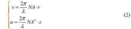
According to the Born and Wolf’s theory [17], at the focal region, the amplitude distribution of a converging monochromatic spherical wavefront passing through the pupil plane can be written as:

Where
Where
Since most practical imaging systems use incoherent illumination, the light intensity distribution near the focal region can be calculated by its amplitude distribution, written as:

Where * denotes the complex conjugate.
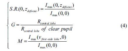
After introducing the phase pupil filter into the optical system, the light intensity distribution will be modulated by the phase changing of the pupil function to realize the DOF extension and superresolution. These can be evaluated by the following three parameters:
1. Defocus Strehl ratio S.R.(0, zdefocus), defined as the ratio of the intensity at the focal point to that corresponding to a clear pupil, is a relevant parameter for analyzing the imaging quality. It is used to evaluate the ability of DOF extension for a pupil filter. Typically, the defocused imaging quality can be considered acceptable when S.R.(0, zdefocus) ≥ 0.8. Thus, the effective depth of focus can be written as DS.R. ≥ 0.8. 2. Superresolution factor G, defined as the ratio of the radius of the central lobe of the intensity distribution to that corresponding to a clear pupil, is a parameter for calculating the spot size reduction. G < 1 means the resolution enhancement for the optical system. 3. Relative first side lobe intensity M, defined as the ratio of between the central lobe intensity and the maximum intensity at the first side lobe, is also a parameter used to evaluate the ability of superresolution for a pupil filter. Typically, M must be limited to less than 0.2 in order not to reduce the resolution and cause energy loss.
These parameters can be written as:
Where
The pupil functions of an optical system with phase only pupil filter can be written as:

Where
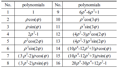
Compared with conventional power functions or Gaussian functions, there are some advantages for pupil filter design by using Zernike functions since they are closely related with optical aberrations. The phase functions with Zernike functions now can be written as:

Where
The first 16 polynomials of the Zernike functions are shown in Table 1 [18].
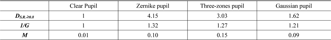
[TABLE1.] Comparison of evaluation parameters for different phase pupil filters

Comparison of evaluation parameters for different phase pupil filters
Here
1. 1st polynomial is a constant, representing the thickness of the pupil filter. Usually, the ratio between thickness and aperture of an optical element is not less than 0.2. Otherwise, the element will be fragile and hard to assemble. 2. 4th, 9th, 16th polynomials represent the defocus, primary spherical aberration and high-order spherical aberration respectively, which are useful to modulate the radius of the central lobe of the intensity distribution. In addition, these three have the ability to reduce the impact of defocus. 3. 5th, 6th, 12th, 13th polynomials represent the primary astigmatic aberration and high-order astigmatic aberration, which can limit the intensity distribution of the side lobe effectively. The 6th term is rotated 45 degrees from the 5th term and the 13th term is rotated 45 degrees from the 12th term. But they make no contribution to the DOF extension and superresolution. In order to simplify the optimization, only 5th, 12th terms are selected to suppress the energy of the side lobe.
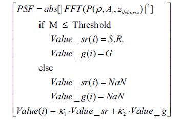
The optimization process is described as follows:
A series of coefficients of chosen Zernike polynomials is used to calculate the PSF of the optical system with the phase pupil filter, and the
If the value of
If the value of
Repeat the above steps, selecting the best comprehensive evaluation result. The corresponding coefficients are the optimization results.
It can be presented as follows by C-type codes:
Iteration:
for{(

end
(
In the optimization,
Thus, optimized coefficients of the proposed Zernike phase only pupil filter can be obtained by a global optimization algorithm, as shown below:
By introducing the designed pupil filter into a conventional optical system with clear pupil, the improvement for imaging quality can be analyzed numerically through calculating the intensity distribution near the focal plane.
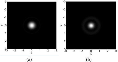
The radial intensity distributions at the focal point are shown in Fig. 1. The coordinates of the figure are in wavelengths. As Fig. 1 shows, the size of the central lobe is compressed by the designed pupil filter compared with the optical system of a clear pupil, which means there is resolution enhancement.
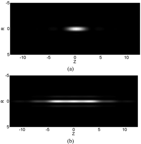
The ability of extending DOF of the Zernike phase only pupil filter can be reflected on the axial intensity distribution across the focal region, as shown in Fig. 2. Similarly, the coordinates are in wavelength. As can be seen from Fig. 2, the length of the bright spot is much longer than that of a conventional optical system, which characterizes the DOF extension.
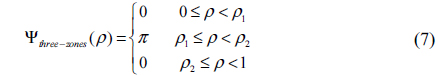
Then, through comparison with the other two pupil filters, advantages of the Zernike phase only pupil filter are shown as follows. Here, forms of the two pupil filters are three zones [10] and Gaussian function [15], their phase functions can be respectively written as:
Three zones:

Where
Gaussian functions:

Where
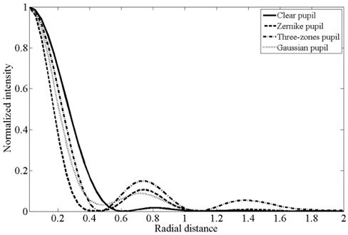
The comparison of radial intensity distributions at the focal point are shown in Fig. 3. It is clearly seen that the intensity distribution with the Zernike phase only pupil filter has the smallest radius of central lobe, which indicates its advantages on superresolution for a conventional optical system. Besides, the maximum intensity at the first side lobe of the proposed pupil filter is constrained quite low, which benefits from the
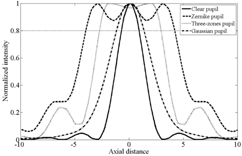
The comparison of axial intensity distributions across the focal plane are shown in Fig. 4. The value of the transverse dotted line equals 0.8, which is used to indicate effective defocus Strehl ratio. That means the imaging quality is acceptable at a certain defocus distance if the corresponding normalized intensity is greater than this value. It can be seen in Fig. 4, the optical system with Zernike phase only pupil filter can keep its normalized intensity greater than 0.8 over the longest range of defocus distance.
The summary of the ability of DOF extension and superresolution for these three pupil filters is shown in the table below. In Table 1, effective depth of focal
In order to demonstrate the ability of DOF extension and superresolution of our designed pupil filter further, imaging simulations are carried out. The virtual object used in the simulations is a resolution testing panel of line pairs with different spatial frequencies. Meanwhile, the defocus distance added in the simulations is from 0λ to 3λ. Results are shown in Table 2. From the first line of these figures in Table 2, the resolution of the optical system is clearly enhanced with all the three pupil filters compared to that with the clear pupil. In performance on DOF extension, the Zernike phase only pupil filter show its advantages. Its imaging results keep quite good quality over the entire defocus distance, which is very useful in numerous applications.
[TABLE 2.] Comparison of defocused imaging for different phase pupil filters
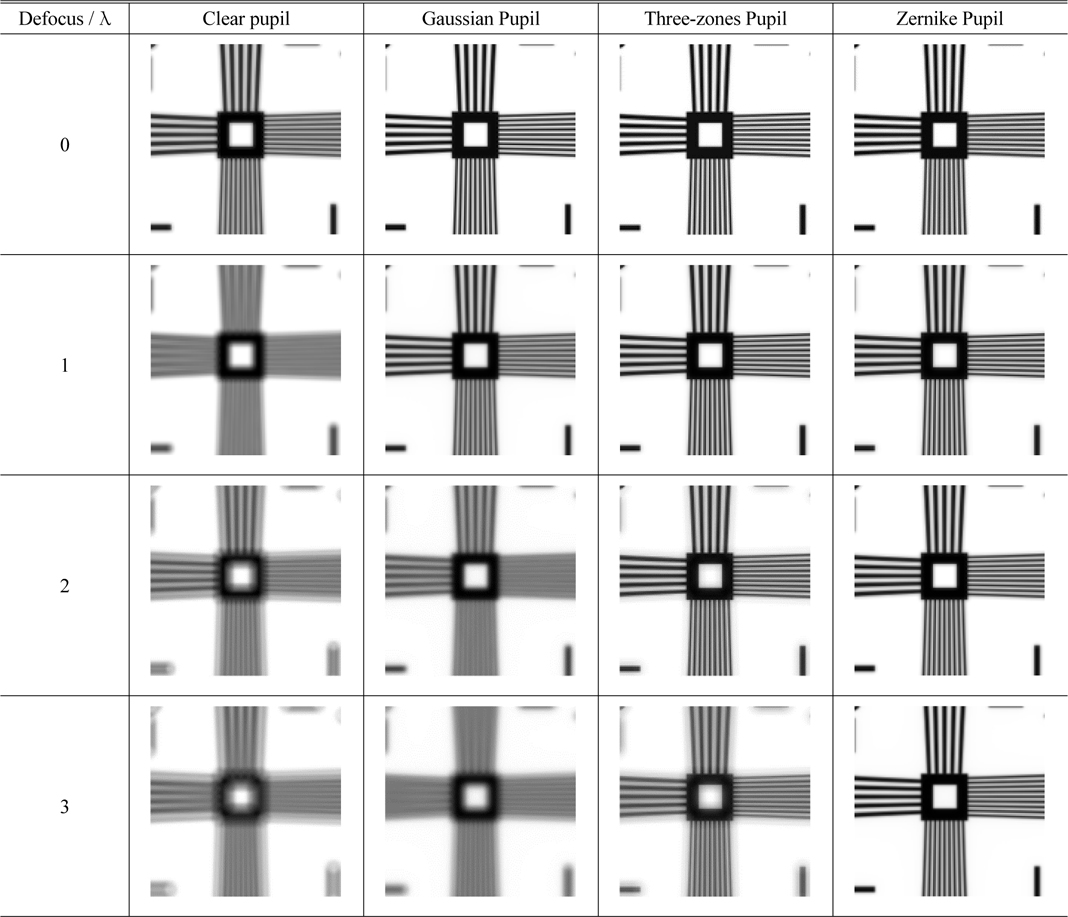
Comparison of defocused imaging for different phase pupil filters
In this paper, we have proposed an optical phase only pupil filter using Zernike functions, used to realize DOF extension and superresolution. Based on analyzing the relationship between Seidel aberrations and Zernike polynomials, design parameters of the proposed pupil filter are optimized. Compared with other two typical pupil filters, the Zernike pupil filter shows its advantages on both DOF extension and superresolution, enlarging DOF 4.15 times and enhancing resolution 1.32 times. Finally, imaging simulations with different defocus distances further demonstrate its effectiveness and superiority on improving the performance of the conventional optical system.