As a new high-capacity short-range wireless technology, visible light communications can meet the needs for lighting and communications [1-3]. In order to meet the needs of communication, multiple transmitters need to be installed on the ceiling. Because of the channel characteristics of visible light, transmitter coverage and reception range of a receiver are usually limited. In multi-user scenario, several transmitters are necessary in order to cover the whole communication area, which may cause severe inter-user interference. Therefore, a proper scheduling algorithm is needed to address this problem. Other problems we are concerned with are user “fairness” and system throughput. A proper scheduling of users depends on the balance of them. One cannot always choose the user with the highest rate, because the users with lower rates would be starved. However, if the users with the lowest rate are chosen, the throughput would drop. The question is how to schedule the resource fairly. Fair scheduling would lower the throughput over the maximum possible, but it would provide more acceptable levels to low-rate users.
The research in the topic is scarce, since the study of scheduling on multi-user scenarios for indoor visible light communications is in an initial stage. Targeting at higher system throughput, a novel full-duplex self-adaptive minimum contention window (SACW) MAC protocol was designed for an indoor VLC star topology network system [4]. This protocol allowed concurrent sending and receiving of data frames between the central node and terminal nodes. It could achieve higher downlink throughput compared with half-duplex operation. A fairness tuning parameter might help balance user fairness and throughput. This goal was achieved through initiatively tuning the parameter in [5]. Ojemba Babatundi
In order to solve the problems we mentioned above, a conflict graph-based scheduling (CGS) algorithm is proposed in this paper. The algorithm consists of two parts. Based on the coverage of each AP, the conflict graph that is also employed to select user sets of non-interference is obtained. Using the conflict graph and the user sets, we design a scheduling scheme to choose the users to schedule for each time slot.
The rest of the paper is organized as follows. In Section 2, we give an overview of indoor VLC system and the problem formulation. We introduce the CGS algorithm in Section 3. The simulation and results are given in Section 4. Finally, we draw the conclusions in Section 5.
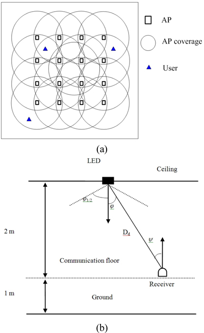
According to [14], compared with the direct received average power of the line of sight (LOS) path, the NLOS-power may be negligible. Therefore only LOS-power is considered as the desired received power for the reason of simplicity. There are several users in the room, their position is randomly distributed. Many APs are mounted on the ceiling, each one of them consists of many LED chips for the purpose of signal enhancement and illumination. A photon detector (PD) serves as a receiver to receive downlink signals. The sensitivity of the PD determines the received signal intensity. The light source is assumed to be Lambert pattern [15]. A typical indoor VLC system model is depicted as follows.
For a given transmitted optical power
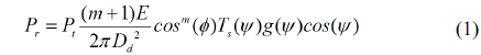
where
where

There are
The

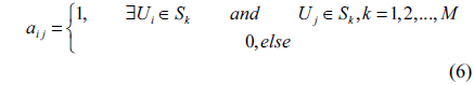
where if user
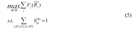
Our goal is to maximize the throughput of the system as well as take into consideration the quality of service (the user fairness), hence the problem formulation can be given as:

where ℜ is the rate region and
III. CONFLICT GRAPH SCHEDULING DOWNLINK RESOURCE
From the previous analysis, we can draw the conclusion that there are three problems that we need to solve. They are interference between users, throughput and user fairness. A conflict graph is employed to solve the first problem-interference. The scheduling scheme is used to achieve the balance between fairness and throughput.
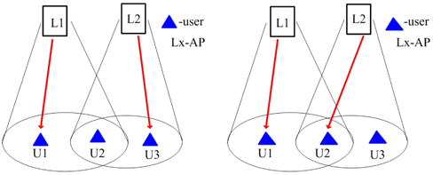
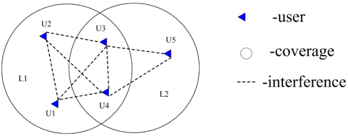
First, let us define the conflict graph. As shown in Fig. 3, there are several users within an AP coverage. They are not allowed to choose the same AP to transmit at the same time slot. Therefore, a dotted line is drawn between them, which means there is interference between them. When all the users are dealt with the same operation, the conflict graph is achieved. Obviously, if there is no dotted line between users, they can choose the same time slot to transmit without interference. Hence the conflict graph can be given as G = <

After the conflict graph is obtained, the next step is to determine the users who are selected to transmit data at the current slot. However this is not an easy task. In order to solve it, the problem is divided into two phases: finding the user sets and choosing one from them.
Phase 1: find the users (we define these users as non-interference user set) who are able to transmit data without causing interferences and more than one set may be found. The goal of this phase is to find all the non-interference user sets. This operation is equal to finding all the maximal independent sets in graph
[TABLE 1.] Process of finding non-interference user sets
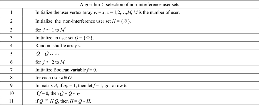
Process of finding non-interference user sets
In Table 1,
Phase 2: in this phase, we focus on selecting a user set from

For each

where R

where Γ is the element number in

where
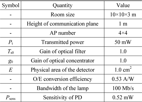
We evaluate the performance of the proposed CGS algorithm from the perspective of the throughput and the user fairness. The scenario is based on a room of size 10 m × 10 m × 3 m. The APs in the room are uniformly distributed as 4 × 4 arrays. Their heights are 3 meters above the floor. All the APs transmit identical power. The height of the receiver is 1 meter. Detailed parameters are shown in Table 2.
[TABLE 2.] Default parameters used in simulation

Default parameters used in simulation
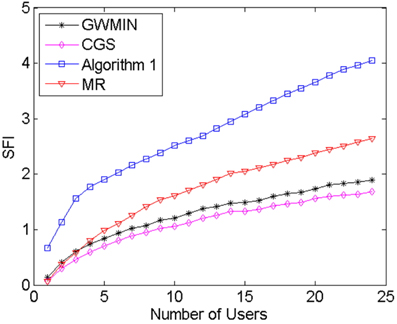
Two parameters are simulated, the throughput and the SFI (Service Fairness Index) which represents the user fairness [16]. The SFI is defined as:
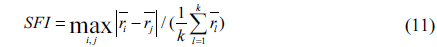
where is the average throughput of
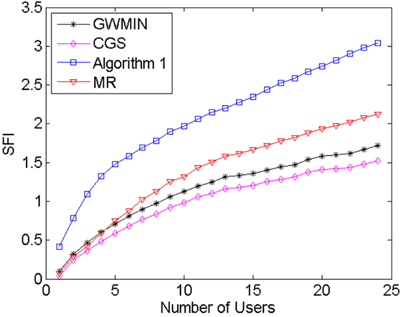
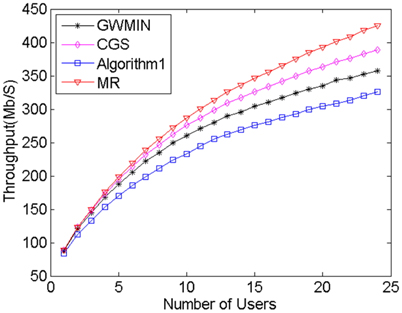
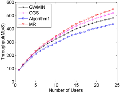
MR algorithm always chooses the maximum rate users without interference. This feature makes its throughput the highest of all algorithms, however its user fairness is the lowest. The meaning of the algorithm is that it reveals the maximum possible throughput. Algorithm1 [9] always chooses the most users without interference. Because this algorithm takes neither throughput nor fairness into consideration, its fairness and throughput are the worst of all algorithms. GWMIN [11] stands for the minimum weight greedy algorithm. Because the greedy algorithm converges locally, the throughput and fairness may not reach its limitation.
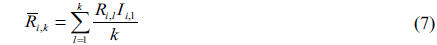
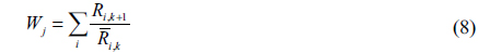
From Fig. 4 and Fig. 5 we can see that proposed CGS has the highest user fairness and better throughput, because in phase 1 the conflict graph ensures that users can transmit data without interference, and in phase 2 the scheduling scheme takes the user rate and average user rate into account, which makes sure of the balance between throughput and user fairness. From Eq. (7) and Eq. (8), when the user rate increases or average user rate decreases, the weight of this user set increases, which makes the possibility of choosing this user set increase. As a result, throughput and user fairness increase; On the contrary, when the user rate decreases or average user rate increases, the weight of this user set decreases, which makes the possibility of choosing this user set decrease. As a result, throughput and user fairness increase. Doing these two operations repeatedly, the balance between the throughput and fairness is achieved.
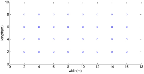
In order to prove the robustness of the proposed algorithm, we would like to increase the number of APs and enlarge the room size. In this configuration, the system environment deployed is an empty room with dimensions 10 m × 18 m × 3 m and there are 4×8 APs installed equidistantly on the ceiling. The vertical view of the layout is shown in Fig. 6. Again we compare the performance of our proposed algorithm with the other three algorithms mentioned earlier. The simulation results are depicted in Fig. 7 and Fig. 8.
Similar to the results in the first configuration, our proposed algorithm has the highest user fairness and better throughput. Moreover, the advantages of our scheme are more obvious with more APs and larger room size. With these numerical results, we would like to demonstrate that the application of our scheme is not limited by the AP number or room size. Our scheduling algorithm is robust to arbitrary AP number or room size.
In this paper, we first give an overview of indoor VLC channel characteristics and the problem formulation. Under the principle of fairness scheduling, a conflict graph-based scheduling algorithm is proposed to improve the performance of downlink resource allocation. Simulations and results demonstrate that our algorithm can achieve the balance between the throughput and user fairness. And time division multiplexing is used to ensure that the algorithm can be applied for a variety of modulation methods.