Many studies have been conducted on dielectric guided-mode resonance (GMR) filters [1], and various practical applications have been suggested such as narrow-line feedback elements [2], biosensors [3], tunable optical filters [4], dispersion engineering [5], polarization beam splitters [6, 7], high power microwave frequency selective elements [8], and color filters [9-12].
Meanwhile, a lot of attention has been given to various types of plasmon-assisted filters after the subwavelength transmission effect through metal holes, which is known as extraordinary transmission, was reported [13-17]. Various types of plasmonic color filters have been proposed, investigated, and demonstrated, with suggestions put forward regarding their application areas [18-27].
A GMR filter can be utilized by plasmons to manipulate light and provide additional functionalities. Recently, metal-insulator- metal (MIM) structures have been employed as a wave-guiding element for GMR filters, and visible wavelength color filters have been realized [28]. Compared to the general dielectric-based GMR filter, the GMR filter employing MIM structures in [28] is more compact and has the embedded functionality of a polarizer, which is advantageous for applications in liquid crystal displays (LCDs) by eliminating the need for a separate polarizer layer. Though it is suitable for the aforementioned application (i.e., in LCDs), it is restricted to applications involving single polarization due the other polarizations being blocked.
To make the best use of the light-manipulation ability of the MIM-type GMR structure, attention must be paid to the fact that the MIM waveguide can support a polarization-selective mode in accordance with the excited plasmon mode at the edge of the metal. This study aims to achieve GMR in both x- and y-polarizations instead of blocking one of the polarizations. Independent color filtering of differently polarized light is possible with a rectangular MIM grating by exciting GMR in both polarizations with the appropriate selection and variation of the material and geometric parameters.
A numerical simulation was performed for the independent color filtering of differently polarized light with the proposed rectangular MIM grating. Independent color filters such as red/green/blue filters for both x-polarization and y-polarization have been demonstrated as examples and their practical application was discussed.
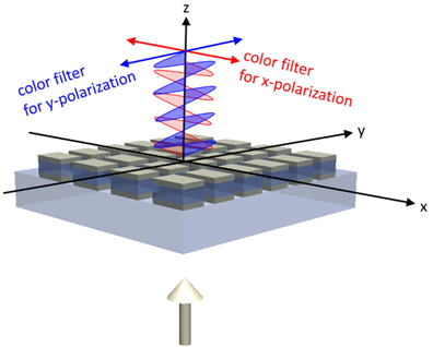
Figure 1 shows a functional description of the proposed independent color filtering of differently polarized light. The proposed structure can work as a red color filter for x-polarized light and a blue color filter for y-polarized light. If unpolarized white light is incident on the proposed structure, red and blue light can be transmitted for x- and y-polarization, respectively.
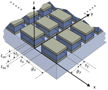
A detailed geometric structure is shown in Fig. 2. Where
The operation principle of the proposed structure is the same as that in [28] except for the diffraction dimension. The proposed structure uses a rectangular-shaped two-dimensional grating while the reference study uses a line-shaped one-dimensional grating. Hence, the proposed structure can support both directions of polarization. However, it is noteworthy that some design considerations must be taken into account to enable GMR in both directions while avoiding interference between the polarizations.
One of the most important considerations is reducing the amount of uncoupled transmission that follows an unintended path without waveguide coupling. The amount of uncoupled transmission is associated with the width of the slit (
The filtering wavelength of x- and y-polarization is determined by the phase-matching condition of Eqs. (1) and (2), respectively.


where
where
III. SIMULATION AND DISCUSSION
The filtering wavelength can be estimated using the GMR phase-matching condition of Eqs. (1) and (2), but the slit width is uncertain. The slit width must be large enough to ensure a sufficient amount of light transmission. However, it should not be too wide because it may weaken the waveguide coupling. To ensure a large transmittance of the filter, the occupation of opening area of the grating must be large without weakening the waveguide coupling by adjusting the refractive index of the insulator of the MIM waveguide. If the refractive index of the insulator is increased, the wave number increases and the grating width can be reduced for the same phase-matching condition. This results in a large occupation of opening area so that the light blocked by the metal can be reduced.
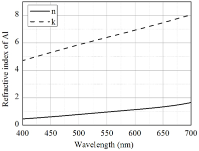
A large slit width also has a negative effect on the spectrum of the other polarizations. To see the influence of the slit width along the y-axis of the filtering spectrum of the x-polarization, a numerical simulation was performed at fixed x-axis parameters while detuning the slit width along the y-axis with a fixed period. Commercial software, COMSOL, was used to solve the electromagnetic wave equation using the finite element method. The simulation parameters for the study are summarized in Table 1. Aluminum was used as the metal layer, and the variation in its refractive index with wavelength is plotted in Fig. 3 [29]. The periodic boundary conditions were set along x- and y-axis directions and the simulation space was meshed symmetrically about both the x- and y-axis to assure accuracy of the calculation. Rectangular-shaped mesh size less than 20 nm was used.
[TABLE 1.] Simulation parameters for calculation
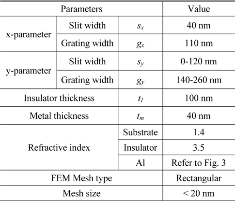
Simulation parameters for calculation
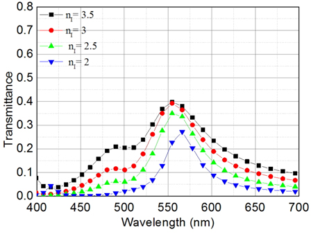
To observe transmittance and bandwidth affected by the refractive index of insulator square shape grating filters were simulated for fixed slit width of
As can be seen in the Fig. 4, transmittance is increased with the high refractive index due to the increased occupation of opening area but the bandwidth is decreased due to the out of coupling (Transmission for x and y polarization are the same in this square shape grating filter because of the same geometric parameter along the x and y axes).
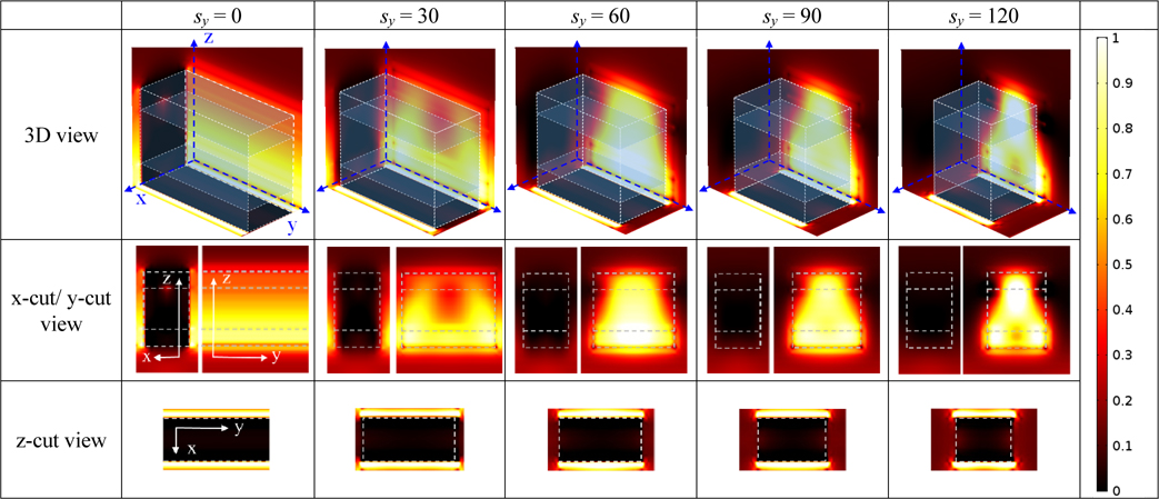
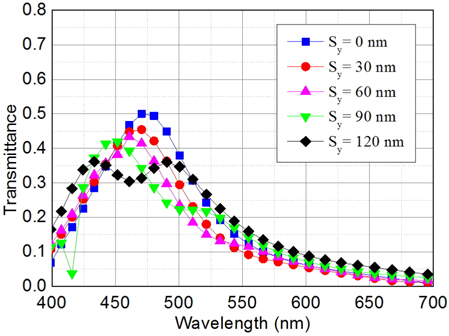
To see the filter characteristic of the x-polarized light influenced by the y axis parameter the transmission (not normalized to the opening area) spectrum of the x-polarization is plotted in Fig. 5, while increasing values of
The time-averaged Poynting vectors (power flow) directing the z-axis are plotted in Fig. 6 for the same conditions in Fig. 5 at ~460 nm wavelength (peak wavelength of the x-polarization at
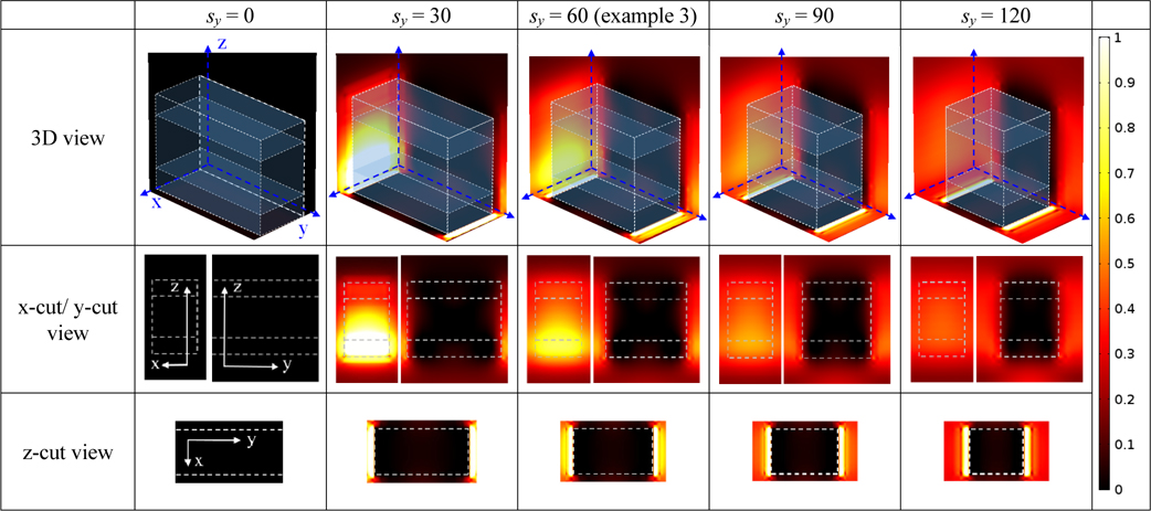
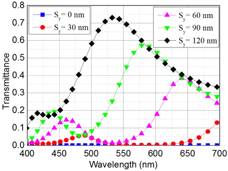
The transmission spectrum of the y-polarization is plotted in Fig. 7 for the same conditions as in the previous study. As
The time-averaged Poynting vectors directing z-axis are plotted in Fig. 8 for the same conditions of Fig. 7 at each peak wavelength (
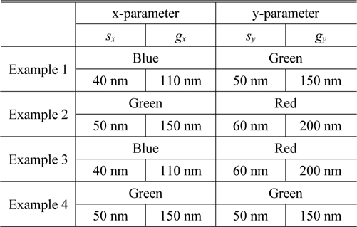
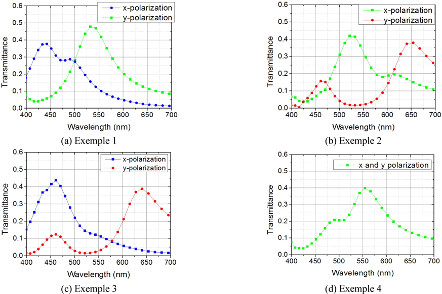
To demonstrate practical applications for independent color filtering, further case studies were carried out for some examples. Examples 1-3 have a rectangular-shaped grating and work as different color filters for each polarization. Example 4 has a square-shaped grating and works as the same color filter for both polarizations. Example 1 works as a blue and green filter for x-and y-polarized light, respectively. Example 2 works as a green and red filter for x- and y-polarized light, respectively. Example 3 works as a blue and red filter for x- and y-polarized light, respectively. Example 4 works as a green filter for both of x- and y-polarized light. The geometrical parameters for these examples are listed in Table 2.
[TABLE 2.] Geometric parameters for examples

Geometric parameters for examples
Figures 9(a), (b), (c), and (d) show the simulated results of Examples 1, 2, 3, and 4, respectively. Transmittance values higher than 35% were achieved for all the designed examples.
From the above study, the opening of
There have been some suggestions of application area utilizing the same function with the proposed device, including chromatic polarizer [30] for polarization imaging and realization of multiple color at the single pixel for ultra-high resolution display or sensor [31, 32]. However, transmittance of the device in reference [31] is very low compared with our proposed device, and color design in the reference [30, 32] is somewhat restricted due to the band stop style of the spectrum.
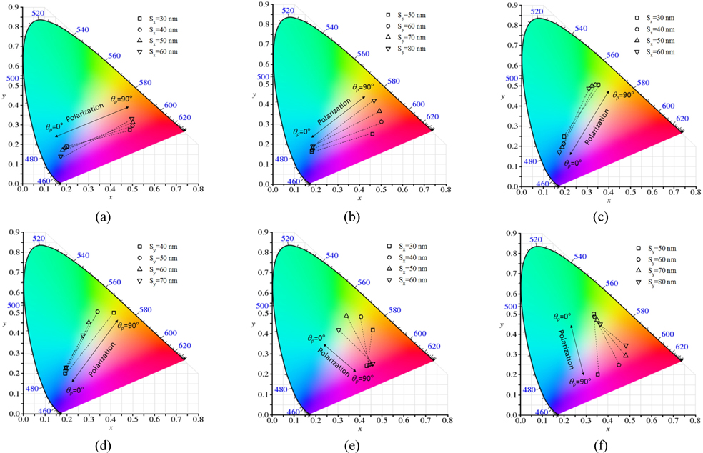
Among these application areas, a feasibility study as a chromatic polarizer was carried out. A chromatic polarizer produces a continuum of colors represented by a line on the CIE (International Commission on Illumination) color space where selection of the transmitted color is made by controlling the polarization of the incident white light [30].
To suggest the reasonable parameters of practical application of our device as a chromatic polarizer, color of the filter spectrum was mapped to the CIE 1931 color space while detuning slit width with the fixed period. Figure 10(a), (b) shows the color map for the designed device in which color of the filtered light is continuously changing from blue (
Figure 10(a) shows color mapping with the variation of the slit width (
Independent color filtering of differently polarized light using the MIM-type GMR structure has been proposed and demonstrated using numerical simulations. A parametric case study was carried out to determine the influence of the slit opening on the filtering spectrum. Blue-green, green-red, and blue-red filters for the corresponding x- and y-polarizations were demonstrated as application examples. The same green filter for both x- and y-polarization was demonstrated as another example. It was shown that a wide slit width could increase the transmittance but reduce the filter quality in terms of the selectivity and increase the interference between each transmission spectrum of polarization. It was shown that the device can be used as a chromatic polarizer by mapping the color of the filter spectrum to the CIE 1931 color space.


![Refractive index of aluminum used as simulation parameter [29].](http://oak.go.kr/repository/journal/20688/E1OSAB_2016_v20n1_180_f003.jpg)