Optical technology for security applications has received increasing interest in the last few decades [1-3]. In particular, the double random phase encoding (DRPE) [1] technique, in which the image is encoded to be a white noise pattern with two statistically independent random phase masks (RPM), has attracted much attention. The DRPE encryption technique is constructed by using two RPMs as keys: one is located at the input domain and the other is at the Fourier domain. To enlarge the key space, it has been further extended from the Fourier transform domain to the Fresnel transform domain [4, 5], the fractional Fourier transform domain [6], the Gyrator transform (GT) domain [7] and the Hartley transform (HT) domain [8], etc. In these encryption systems, the parameters (e.g. the propagation distance, the fractional order, etc) are introduced and served as extra keys. Since the HT is mathematically equivalent to the Fourier transform but is purely real, it has a computational advantage over the aforementioned transforms for not having to manage the real and imaginary parts [9]. Though most of the DRPE-based encryption techniques are quite robust and secure, the recovered image loses its color information, which is useful in image processing and practical applications, and in decryption since the original image is illuminated with monochromatic light [10].
Using the DRPE technique, Zhang and Karim reported a single-channel encryption algorithm for color image in the Fourier domain [11]. Chen
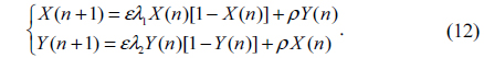
In this paper, based on the quaternion Hartley transform (QHT), logistic-based scrambling technique, GT-based DRPE and three-step phase-shifting interferometry (PSI), a novel hybrid color and grayscale image encryption method is presented. In the proposed approach, the QHT is defined and its calculation for a quaternion matrix is developed first. Then a color image and a grayscale image are processed holistically in a vector manner using QHT. To resist an attack such as chosen plaintext attack, the components of the QHT-transformed images are permuted by use of the designed scrambling algorithm based on logistic maps. Since the flexible configuration of the GT based system, which means fixed distances between the generalized lenses and the manipulation of the transformation angle using lens rotation, makes the setup useful for image encryption [19], the GT-based DRPE technique is used to encrypt the images after QHT and permutation. The resulting encrypted signal from the cryptosystem is recorded as interferograms by the three-step PSI. Numerical simulations have been made for demonstrating the feasibility and performance of this encryption.
In this section, we come back to some related theories before extending the traditional HT to the quaternion domain, showing how to calculate the QHT of a quaternion matrix and developing the logistic maps-based scrambling technique, etc.
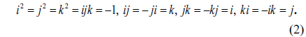
Quaternions can be viewed as generalizations of complex numbers. A quaternion number can be represented as follows [18]:

where
The conjugate and modulus of a quaternion are respectively defined by

When
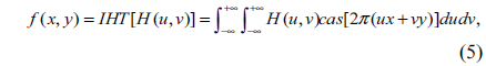
In mathematics, the HT, which transforms real-valued functions to real-valued functions, is an integral transform closely related to the Fourier transform. HT has two main properties: one is that it is a real transform; the other is that it and its inverse transform are identical [21]. Therefore it can have computational advantages over the Fourier transform [21]. The HT [8] of a real function
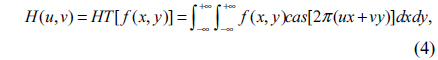
and the inverse Hartley transform (IHT) is defined as

where
2.3. Double Random Phase Encoding in the Gyrator Domain
In mathematics, the GT with respect to parameter
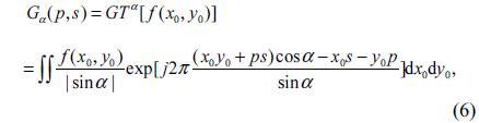
where the

where
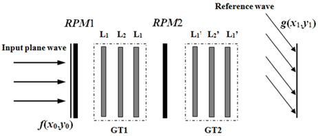
In Fig. 1, the optical setup of DRPE in the gyrator domain is shown. Three planes are defined as the input plane, the transform plane, and the output plane. The corresponding coordinates of the three planes are denoted by (
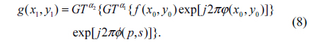
By applying IGT to the encrypted data with the conjugates of the

2.4. Phase-shifting Interferometry
Since digital holography [2] provides a convenient form of recording the complex encrypted images after passing through the DRPE systems, phase-shifting interferometry is employed to record the complex resulting encrypted signal in the proposed scheme. A variety of PSI techniques have been developed, including three-step, four-step, etc [23].
Let

For a known set {

Chaos theory is an evolutionary theory, which describes that the nonlinear dynamical systems change from ordered state to disordered state [26]. The dynamical systems are established based on various chaos functions such as logistic maps, which are extremely sensitive to the initial conditions. These functions generate iterative values which are completely random in nature. In this paper, the two-dimensional (2D) logistic map is used to make the change of sequence of image pixels. It is defined as [26]
The dynamic behavior of 2D logistic is controlled by the parameters
III. QUATERNION HARTLEY TRANSFORM
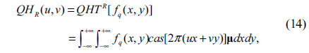
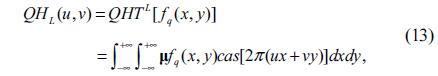
Due to the non-commutative multiplication property of quaternions, there are different types of QHT that can be defined. In this work, the left-side QHT (QHTL) and the right-side QHT (QHTR) are defined:
• Left-side QHT:
• Right-side QHT:

where
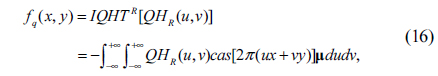
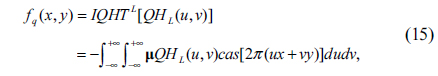
Corresponding to QHT, two forms of the inverse QHT (IQHT) are defined as follows
• Left-side IQHT (IQHTL):
• Right-side IQHT (IQHTR):

Here,
In this sub-section, the method which makes full use of the existing HT algorithm to calculate the QHT of a quaternion matrix is presented. Since the left-side QHT is used in this work, only the calculation method for it is described. By using the HT algorithm, the QHT can be implemented efficiently.
Since

where
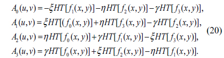
For left-side QHT, substituting (17) into (13), we have
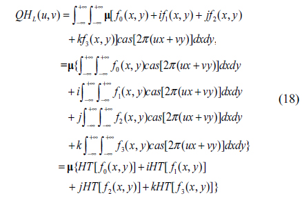
Considering the general unit pure quaternion µ=

where

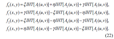
Similarly, applying left-side IQHT to Eq. (19), the reconstructed
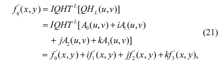
where

It can be observed from formulas (18)~(22), the left-side QHT and IQHT of a quaternion matrix can be calculated effectively by using the traditional HT and IHT algorithms. Notice that the right-side QHT can be processed in a similar way.
IV. THE 2D LOGISTIC MAP-BASED IMAGE SCRAMBLING METHOD
By using a scrambling technique, He
Let
1) Calculate the height
2) Initialize
3) Generate two integers
4) Compute the chaotic sequences
where round(
5) Sort the sequences
6) Map
7) Use the permutation indices

8) Finally, the scrambled image
The inverse image scrambling process is similar to the image scrambling process. In decryption (inverse scrambling process), obtain the permutation indices

Finally, the decrypted image
V. THE PROPOSED HYBRID COLOR AND GRAYSCALE IMAGE ENCRYPTION AND DECRYPTION
Let

where
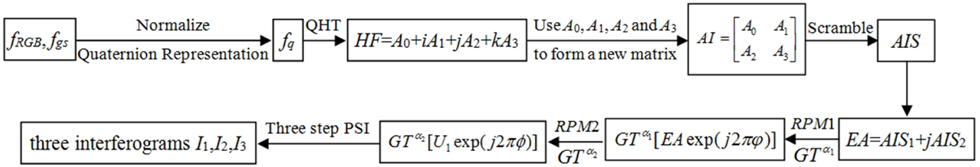
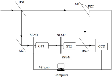
Therefore, based on the QHT, the scrambling method and the GT-based DRPE, a hybrid color and grayscale images encryption scheme is proposed. In the proposed method, the three step PSI is used to record the encrypted data. The optoelectronic setup of the proposed encryption process is shown in Fig. 2. Supposing
1) Normalize
2) Apply QHTL to fq(x,y):
Here,
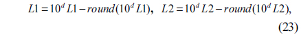
3) With

Since the length and width of
4) Permute
5) Let
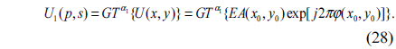
6) The complex amplitude
7) As shown in Fig. 2, import

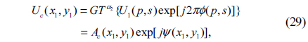
8) Subsequently, the complex function

where
9) For convenience of storage and transmission, the object wave and reference wave overlap to produce real-valued interferograms. As shown in Fig. 2, the resulting encrypted data is recorded as three interference patterns
In the encryption process mentioned above, the steps (1)~(6) will be performed digitally. In Fig. 2, M1, M2 are mirrors, and BS1 and BS2 are beam splitters. GT1 and GT2 are corresponding to the gyrator transform systems GT1 and GT2 shown in Fig. 1, respectively. As shown in Fig. 2, the complex function
The parameters of the proposed encryption method, including
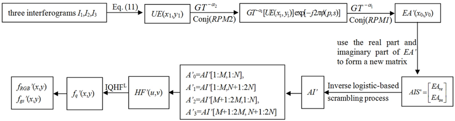
The decryption process, which is similar to the encryption process, but in the reversed order is depicted as follows:
1) Using the three interferograms
2) Apply a GT to
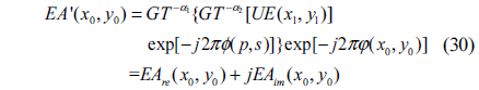
3) Make another GT with order -

where
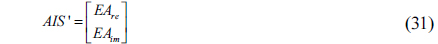
4) With

5) With the parameters
6) First, let
7) Apply IQHT to
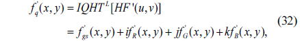
8) With the normalized
Figure 4 depicts the decryption process. In Fig. 4, conj(
VI. NUMERICAL SIMULATION RESULTS
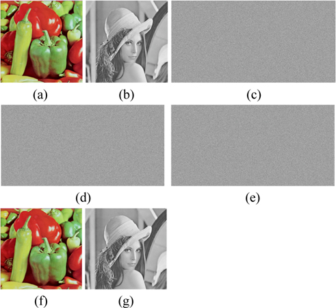
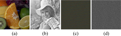
To verify the feasibility of the proposed encryption technique, numerical simulations are performed on the color image “Peppers” and the grayscale image “Lena”, which sizes are both 512×512, shown in Fig. 5(a) and Fig. 4(b). We carried out tests on a notebook computer with Intel(R) Core(TM) i7-4700HQ CPU @ 2.40GHz and 8G DDRL3 and with the MATLAB R2013a. In the experiments, the system parameters are µ=(

where,
6.1. Performance of the Encryption System
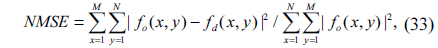
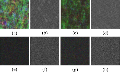
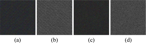
Using the proposed encryption scheme, the “Peppers” and “Lena” are encrypted and three encrypted interferograms are obtained, which are shown in Figs. 5(c)~5(e). Figs. 5(f)~5(g) display the retrieved color and grayscale images with the correct keys respectively, which are perfect, without any noise or distortion. As shown in Table 1, the NMSE between Fig. 5(a) and Fig. 5(f) and that between Fig. 5(b) and Fig. 5(g) are 1.7017×10⁻³⁰ and 1.173×10⁻³⁰, respectively.
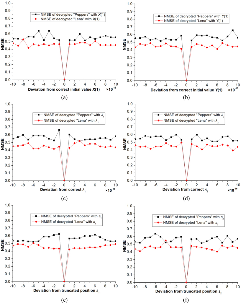
Now we investigate the sensitivity of retrieved image to small change of the parameters of 2D logistic map-based scrambling technique on the decrypted results. Figure 6 showed the derivation of NMSE versus the parameters
The corresponding NMSEs are listed in the upper part of Table 1. Please note that in the above experiments, the other keys remain correct while a key is changed in decryption. As illustrated in Figs. 6(a)~6(d) and Figs. 7(a)~7(h), we cannot obtain any information from the decryption images visually when the absolute values of deviations of
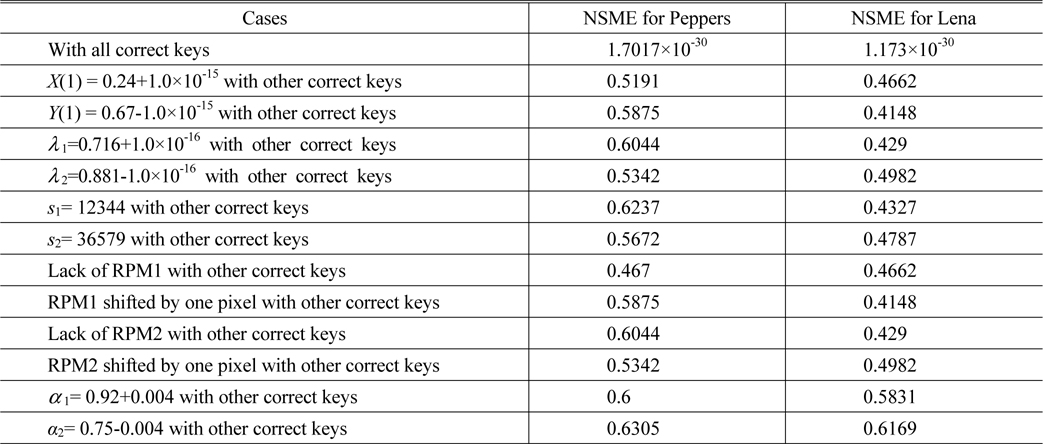
Comparison between the NSMEs of the decrypted “Peppers” and “Lena” by use of correct and incorrect keys
In the experiments, one of the two
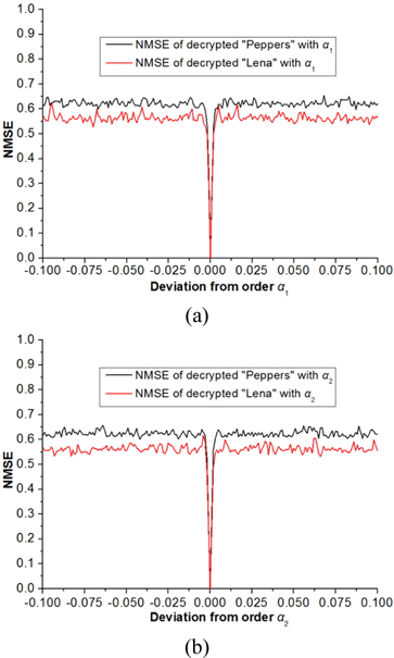
To examine the sensitivity of small change of the orders of the GT, the decryption processes are performed by fixing one order and varying the other. The relationship curves between the NMSE and the deviation of the GT order are shown in Fig. 9, in which the deviation ranges from -0.1 to 0.1 and the step is 0.001. As can be seen from Fig. 9, the NMSE value approximates to zero when
Next we estimate the key space of the proposed encryption scheme. According to the description of the proposed method, we know that the key space of the cryptosystem consists of the
6.2. Robustness of the Method Against Attacks
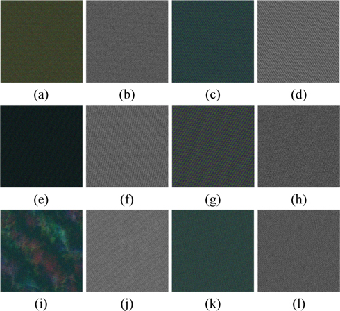
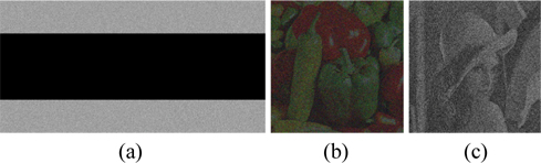
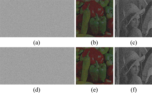
Information loss or noise contamination may occur during data transmission. Now, the robustness of this scheme against occlusion attack which is regarded as data loss is tested. Figure 11(a) shows one of the interferograms occluded by 50%. The recovered images obtained with all correct keys are illustrated in Figs. 11(b)~11(c). It’s well known that Gaussian noise [33] and salt & pepper noise [33] are frequently appearing noises during the information transmission. The robustness test is further verified against noise attacks on the encrypted results. Figure 12(a) is one of the interferograms distorted by Gaussian noise with mean value 0 and standard deviation 20. The corresponding retrieved images are displayed in Figs. 12(b)~12(c). Fig. 12(d) exhibits one of the interferograms damaged by salt & pepper noise with density 0.02 added. Figs. 12(e)~12(f) depicts the corresponding retrieved images. Although all the results shown in Figs. 11(b)~11(c), Figs. 12(b)~12(c) and Figs. 12(e)~12(f) are interfered with seriously by noise and the corresponding NMSEs are big, the secret images among the noise fluctuation can still be distinguished.
Four attacks, including cipher only attack, known plaintext attack, chosen plaintext attack and chosen ciphertext attack [32], are often used to attack the DRPE-based optical security system to recover the ciphered images. Among these attacks, the chosen-plaintext attack is the most powerful attack [32]. He
In the numerical simulation, the encrypted results were obtained by computer. So the computational complexity of the proposed encryption technique is calculated. The calculation depends on three main factors. First, to deal with a color image and a grayscale image holistically in a vector manner, the QHT is computed one time. According to the developed calculation method in sub-section 3.2, the QHT can be implemented via calculating HT four times. For an image with size
In the paper, a novel definition of quaternion Hartley transform and its implementation are presented first. Then a new method for hybrid color and grayscale images encryption is proposed, in which the QHT combined with the developed chaos-based pixel scrambling technique, the GT-based DRPE and the three-step PSI is used to encrypt the color and grayscale images. By use of QHT, a color image and a grayscale image are processed holistically in a vector manner without separating the color image into three channels and manipulating the grayscale image independently, so that the complexity of the security system can be reduced effectively without any reduction of its security. The components of the QHT-transformed original images are combined as the complex amplitude which will be strengthened the nonlinearity by the designed chaos-based scrambling technique and encrypted by the GT-based DRPE technique. In addition, the encrypted interferograms which are recorded by three-step PSI are real-valued, so they are convenient for storage and transmission. One needs to specify all the right keys to recover the original images correctly. Simulation results demonstrate that the proposed scheme has a quite sensitivity to the decryption keys, a enormous key space to resist brute force attack and a good robustness against Gaussian noise, salt & pepper noise and some attacks such as chosen plaintext attack.