The rate of energy usage around the world is increasing. There is also a growing interest in renewable energy to help overcome problems related to fossil fuel depletion, climate change, and environmental pollution [1-3]. Renewable energy includes geothermal, wind, and wave power generation. These, however, are difficult to install and show a big difference in power generation output according to location conditions [4,5].
However, a photovoltaic(PV) power generation system, is easy to install and operate in comparison with other systems, and uses the light of the sun as energy source. Accordingly, it is not largely dependent on local conditions. Therefore, solar has received substantial attention from the private sector [6,7]. Photovoltaic power generation can create continuous and infinite energy by converting sunlight into electrical energy. Accordingly, it has received attention as an alternative to fossil energy. Korea has pushed forward with the supply of renewable energy through government projects supporting photovoltaic installations. Photovoltaic systems are classified into grid-connected systems and stand alone systems according to the method of use [8].
The stand alone system is when the power generated from solar cells is stored in a battery, or it is directly connected to a device. This is mainly used for small devices such as streetlights.
The grid-connected system is a system where DC generated from solar cells is converted into AC (alternating current), and is supplied to electric power installations. This system can supply electric power to consumers from traditional power installations when solar electricity is insufficient due to environmental factors. In the case of domestic photovoltaic power generation, a solar module is installed on the roof and enables electrical power production of 3~5 kW, and is incorporated into an on-grid system [9]. In an on-connected solar system used for a house, a solar cell module is installed on the rooftop for maximum solar radiation. It is composed of a junction box, and an inverter for converting the power from DC to AC.
In cases where DC solar cells are directly connected to an inverter, a conflict between modules occurs due to load variation. In this case damage to the solar cell module, due to reverse current, may occur. In order to prevent this, a junction box is used. A junction box collects the DC power generated by the solar cells and transmits it to an inverter. The box plays a simple role of stopping the direct current supplied to the inverter with fuse, in case something goes wrong. However, solar cells are connected in parallel so, a voltage difference between modules occurs. In order to make up this difference, a reverse voltage cutoff diode is used. The use of the reverse voltage cutoff diode leads to temperature increases inside the junction box. The accumulation of heat leads to a short circuit, and electric leakage occurs through the breakdown of the insulation component.
The methods described here enable the control of temperature inside the junction box using a heat sink. Characteristics of heat generation were analyzed after developing a junction box that could minimize heat generation by designing the box so that excess electric current from the photovoltaic cells didn't pass through the reverse voltage diode.
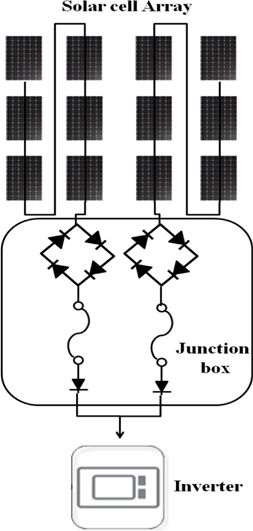
The power generation capacity of domestic photovoltaic installations, in general, are based on electric power production of 3kW class and 300 kWh per month. In the case of the solar module, its electrical characteristics are classified according to the type, number, efficiency, etc. of cells that the module is composed of. Generally, home-based solar modules are composed of 12 cells. The maximum nominal open voltage is approximately 34~40 V. Therefore, in cases where 12 modules are connected in series, 400 V or higher of DC is generated. Accordingly, earthing resistance should be designed so that it is 10 Ω or below for safety. Because of this, 6 modules are connected in series and a parallel circuit is created and used. Figure 1. shows the block diagram of a typical domestic photovoltaic power generation system.
A junction box in a photovoltaic power generation system is composed of a fuse for overvoltage blocking and a diode for reverse current protection. The diode protects the system from a reverse voltage that can be generated due to a voltage difference between installed modules. Heat is generated due to the normal flow of direct current. The accumulation of heat in a junction box frequently causes a short circuit and electric leakage through the breakdown of component insulation. In order to solve these problems, a heat sink is used. However, it is necessary to reduce the heat generation.
Due to the characteristics of photovoltaic power generation, the highest power outputs are be achieved in the afternoon when there is a large amount of solar radiation. Accordingly, a junction box was constructed so that electric power is directly supplied to an inverter, without passing through a diode, at a point when high voltage and large current was generated in order to minimize the heat generated from the component.
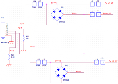
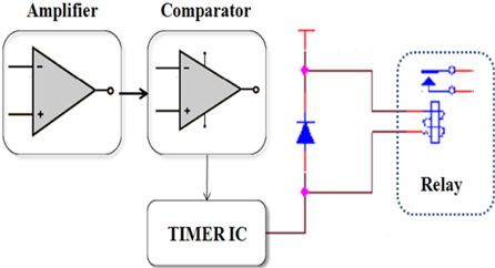
Figure 2 shows the circuit diagram of the low heat generating junction box which enables the bypass of high voltages. The junction box was composed of 2 channels. The amount of current supplied from the module was measured. And the junction box was constructed so that the current could flow without passing through a diode, if a current at a certain level or above flowed. Terminals for the bypass of current are made in J8, J70, J7, J71, J16, and J19. The junction conversion was made, using a 2-channel relay. A circuit for controlling the relay is shown in Figure 3. The domestic low-heat generating photovoltaic power generation system used in this study was composed of 2 channels.
It was composed of 2 relay control circuits. A control signal used for shunt resistance made in R20 and R26 which was used for checking the amount of current generated in 6 solar cell modules connected in series. It was constructed so that the micro voltage signal measured in the shunt resistance was amplified approximately 10 times so that the voltage could be easily compared.
The amplified signal is sent to a timer IC (integrated circuit) through the comparator. And the signal controls the relay so that the current can be directly transmitted to an inverter without passing through the reverse voltage diode, in case a current of 1.5 A or above is generated.
In this study, a comparison of a generally utilized junction box and low heat generating junction box was made. In order to control the outside environment in the same condition, a constant temperature & humidity chamber (TH-402HA-1, ETAC, Japan) was used. The internal temperature was set for 50±2℃. A certain load was applied to a junction box inside the constant temperature & humidity chamber, and then a change in the temperature of the heat sink was measured. DC 25 V was applied to the input terminal of the junction box using a power supply (XDC60-100, XANTREX, Canada), so that the load was similar to one applied in a photovoltaic module. 20 A of current was applied using DC electronic lode (PLZ1004 W, KIKUSUI, Japan) so that a constant current always flowed through the junction box. To measure the change in temperature, a recorder (MV2000, YOKOGAWA, Japan) was used. Change in the temperature of the heat sink were measured for 6 hours, using a K-type sensor.
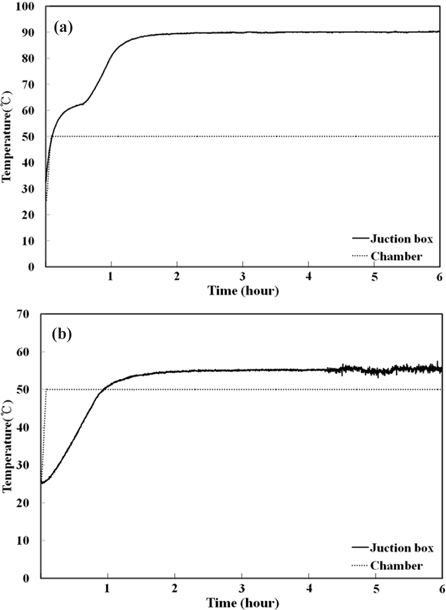
Figure 4 shows the change in the temperature of general junction box and low heat generating junction box.
With regard to conditions inside the constant temperature & humidity chamber, approximately 8 minutes were required to reach the set temperature of 50℃ from room temperature.
The temperature of the heat sink in the general junction box showed a sharp increase in temperature twice. As for the general connection board, the primary temperature rise showed a rapidly rising curve up to about 60℃. It is judged that this was caused by the rapid temperature rise and heating element in the chamber. The secondary rise was the result of the accumulation of heat from the internal element. For the general junction box, approximately 90℃ was measured during the experiment after the 2nd increase.
As for the temperature rise of the general connection board compared to the low heat connection board, a constant temperature was maintained after about 1 hour and 20 minutes to 30 minutes after measurement, and did not show a rapid rise.
In comparison, the low heat generating junction box kept the temperature of the heat sink at 55℃ which was higher by 5℃ than the set temperature of the chamber.
Heat was not generated from the diode since a large amount of current was directly transmitted to an inverter without passing through the diode.
In this study, a low heat generating junction box showed where the temperature of heat sink decreases by approximately 35℃ decrease in temperature when compared comparison with that of standard junction box. And it can decrease heat generated in reverse voltage diode when a large amount of current is used at high voltage.
This paper describes a junction box which incorporates a high electric power bypass circuit in order to reduce heat when used for 3 kW-class domestic photovoltaic power generation system. The performance was also evaluated.
Photovoltaic modules with 2 channels, constructed in parallel, were used. Accordingly, a diode for reverse voltage protection was included for ensuring the safety of the photovoltaic modules. However, the use of the diode for reverse voltage protection causes trouble in the junction box when temperatures rise as high electric power is generated. Therefore, an analysis was made by comparing the temperature distribution of the heat sink with that of a general junction box after manufacturing a low heat generating junction box in which a bypass circuit was built so that electric power could be generated without passing through a reverse voltage diode in case high electric power was generated in photovoltaic power generation.
The temperature of heat sink in the standard junction box was approximately 90℃, and approximately 55℃ in the low heat generating junction box. This is a difference of approximately 35℃. This difference is the result of a reduction in the heat generated by the reverse voltage diode due to the use of the bypass circuit when high electric power is generated. It is expected that the low heat generating junction box will prevent accidents due to heat generation and will provide easier maintenance to home photovoltaic installations.