With the development of society, traditional fossil energy can no longer meet needs, and the consumption of traditional fossil energy will bring a series of environmental problems. Therefore, the development and utilization of new clean energy has attracted worldwide attention. As an inexhaustible source of energy, solar energy has received more and more attention. As a kind of effective way to utilize solar energy, the solar-pumped laser has become one of the hot spots in the field of laser technology in recent years [1, 2]. Solar pumped lasers have great prospects in fields of space solar powered stations, space laser communication, laser propulsion, military and photochemistry [3].
The pumping configuration of solar lasers can be divided into end-pumping, side-pumping and hybrid-pumping. Concentrating systems also can be imaging or non-imaging optical systems. Solar end-pumping was adopted earlier [4]. In 1992, Dave Cooke used a telescope mirror as a first-stage concentrator for end-pumping, which achieved a laser output of more than 3 W [5]. A Fresnel lens was used to achieve the end-pumping of the solar laser in 2007. The output power was 24.4 W [6]. In 2009, Jianwei He reported a solar end-pumped Nd:YAG laser of which the concentrator was also a Fresnel lens [7].
Side-pumping is also a common pumping method. In 2003, Lando reported a solar side-pumped laser with concentrator composed of a primary mirror and a two-dimensional CPC. The output power was 46 W [8]. In 2014, Dawei Liang demonstrated a concentration system consisting of four Fresnel lens-folding mirrors, four fused quartz crystals, four 2D-CPC and four V-shaped cavities to realize the side-pumping of a Nd:YAG laser rod. The output power was 59.1 W through theoretical analysis [9]. In 2016, Dawei Liang reported a concentration system which was composed of a heliostat-parabolic mirror, an ellipsoidal fused silica concentrator and a 2V-shaped pumping cavity. The output power of TEM00-mode is 4.5 W [10]. In 2017, S. Mehellou used a heliostat-parabolic mirror system, twisted optical waveguide, 2D-CPC and V-shaped cavity to pump the side of the laser rod, resulting in a 2.7 W laser output [11]. In 2019, 5.40% slope efficiency of a solar laser was achieved by side-pumping of a 3 mm diameter, 30 mm length Nd:YAG crystal rod with a concentration system which was composed of a heliostat-parabolic mirror, a fused silica aspheric lens, and a two-dimensional semi-cylindrical pump cavity [12].
Hybrid-pumping is also an effective method if the concentration efficiency of end-pumping or side-pumping is not high enough. In 2013, J. Almeida demonstrated a concentration system consisting of a heliostat-parabolic mirror, a conical-shaped light guide, a 3D-CPC and a conical cavity to pump the laser crystal and a laser output of 40 W was obtained [13]. In 2015, J. Almeida used a cone-shaped fused silica lens to further converge sunlight from heliostat-parabolic mirror into a conical pump chamber and 56 W laser output power was obtained [14]. In 2016, Dawei Liang used a parabolic concentration system, a fused silica aspheric lens and a conical pump cavity to pump the Nd:YAG laser rod. The CW laser output reached 29.3 W [15]. In 2017, 37.2 W continuous-wave multimode laser output was also demonstrated with this concentration system [16]. In 2018, Dan Fang obtained a laser output of 3.5 W with a concentration system consisting of a Fresnel lens, conical condenser and conical pump cavity [17]. In 2018, Z. Guan reported a solar concentration system which was composed of a Fresnel lens and a gold-plated conical pumped cavity. 33.1 W continuous wave output laser power was obtained [18]. In 2019, Vistas achieved a 24 W multimode laser output through a concentration system consisting of a heliosta-parabolic mirror system, a fused silica liquid light guide lens and a conical pump cavity [19].
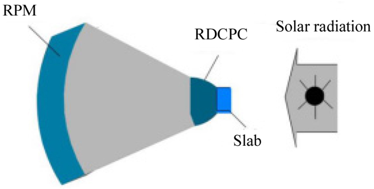
However, for the high-power solid-state lasers based on cylindrical laser rod, high temperature at the central axis and a serious thermal effect can make beam quality worse [20, 21]. So, reducing the thermal effects becomes a major problem to be solved in order to meet the requirements of high power and high beam quality in laser output [22]. Because the temperature gradient occurs in the thickness direction of the slab, the thermal lens effect and the thermooptical distortion effect can be reduced substantially in the slab laser, and the laser output power would be improved greatly [23]. However, the difficulty of designing the concentrator increases because the thickness of the slab is smaller than the diameter of the laser rod. In order to realize the solar side pumping of a slab laser, in this paper, a two-stage concentration system composed of RPM and RDCPC is proposed to collect solar radiation on the side of the slab Nd:YAG crystal.
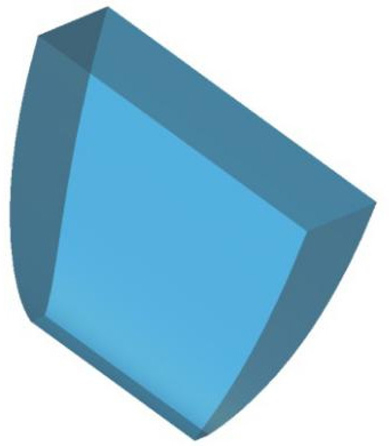
The structure of the solar slab laser concentration system proposed in this paper is shown in Fig. 1. The concentration system consists of an RPM and an RDCPC. The slab-shaped gain medium was placed behind the RDCPC. The direction of solar radiation is parallel to the axis of the parabolic mirror.
The non-imaging concentration system of the solar side-pumped slab laser was designed according to the principle of the edge ray. The concentrating efficiency and the uniformity of the converging spot were mainly considered. The design method of concentration system is as follows: (1) The outlet size of the secondary concentrator is 2 mm × 20 mm, which is the same as the side of the slab laser medium. (2) The edge ray reaching the primary concentrator is reflected to the inlet of the secondary concentrator. (3) The secondary concentrator called rectangular dielectric-filled compound parabolic concentrator (RDCPC) needs to converge the light as much as possible to the outlet. It requires the RDCPC not only has the larger inlet area, but also has a larger maximum acceptance angle.
The RPM is used as the first-stage concentrator. Compared with a transmission concentrator (such as a Fresnel lens), the dispersion is not considered in the design and only the divergence angle of the sunlight needs to be considered. Dispersion has a great influence on the concentrating effect of the Fresnel lens. For example, the sunlight passes through a rectangular Fresnel lens based on the material of PMMA, and the focal length, groove pitch, thickness and size of the Fresnel lens are 1200 mm, 0.33 mm, 3 mm, 1400 mm × 1050 mm, respectively. Because of the dispersion, the spot on the focal plane of the Fresnel lens is larger and it makes the concentration efficiency lower. Even if the laser rod has a radius of 7 mm, the total concentration efficiency is only 50% [24].
III. THE DESIGN OF THE CONCENTRATION SYSTEM
3.1. The Design of the Primary Concentrator
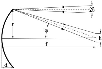
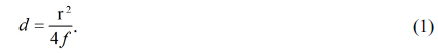
As shown in Fig. 2, incident sunlight has a divergence angle of 32'. It was reflected by a parabolic mirror to form a spot. The Eq. (1) was obtained from the parabolic equation:
The following equations can be obtained from the geometric relationship and the law of reflection:
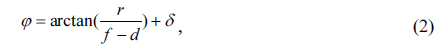

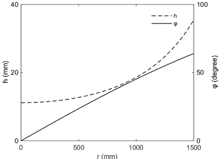
where φ is the included angle between the edge light reflected by the parabolic mirror and the central axis, h is the diameter of the focused spot, r is the radius of the parabolic mirror, and d is the height of the parabolic mirror.
The relationship between the h, φ and r was shown in Fig. 3. The spot diameter h and angle φ increase as the radius of the parabolic mirror increases. The spot diameter h increases slowly when r is in the range of 0~1000 mm, and h increases quickly when r is in the range of 1000~1500 mm. If the parabolic mirror is circular, the reflection angle φ is constant. It is not conducive to the further compression of the spot by the secondary concentrator. Considering the size of the pumping surface of the slab laser, an RPM with a size of 734 mm × 2000 mm acted as the primary concentrator.
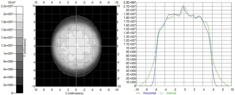
The concentrating effect was simulated with TracePro optical software. The irradiation map of the focal spot is shown in Fig. 4 with the sunlight passing through the primary concentrator. The focused spot is approximately elliptical. If a 2 mm × 20 mm receiving surface is placed on the focal plane, the concentration efficiency is only 21.9%. It obviously cannot meet the requirements by using only a primary concentrator, so it is necessary to add a secondary concentrator for further condensing.
3.2. The Design of the Secondary Concentrator
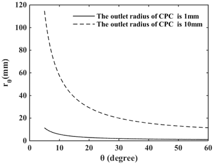
The parameters of a CPC include the outlet radius

If the maximum acceptance half angle of the CPC and the outlet radius were given, the radius of the inlet can be calculated by the above formula. The structure of the entire CPC can be obtained.
It can be seen from Fig. 3 that the spot diameter h is 18.6 mm and the angle φ is 45.5° when the sunlight passes through the edge of the RPM with a width of 2000 mm. The spot diameter h is 12.0 mm and the angle φ is 17.7° when the sunlight passes through the edge of the RPM with a width of 734 mm. Obviously, the size and uniformity of the spot in two directions need to be further improved. In order to realize the solar side-pumped slab laser, the outlet of the CPC was set to rectangular. The rectangular compound parabolic concentrator (RCPC) as the secondary concentrator was proposed first.
In order to match the outlet size of the secondary concentrator with the pump side of the slab, the outlet of the RCPC can be set to a rectangle of 2 mm × 20 mm. When the outlet size of the RCPC is determined, there are two design methods for the structure of the RCPC. One is to calculate the inlet size of the RCPC by regarding the angle of φ as the maximum acceptance half angle
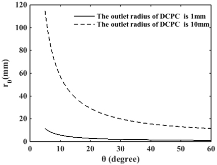
The relationship between inlet radius
In order to solve this problem, the RDCPC filled with BK7 was proposed. The relationship between the inlet radius of this DCPC and the maximum acceptance half angle is shown in Fig. 6. Comparing Fig. 5 with Fig. 6, it can be seen that when the outlet radius and the maximum acceptance half angle are the same, the inlet radius of the DCPC is significantly larger than that of the conventional CPC. When the outlet radius of the DCPC is 1 mm, the corresponding angle φ is 17.7° and the maximum acceptance half angle
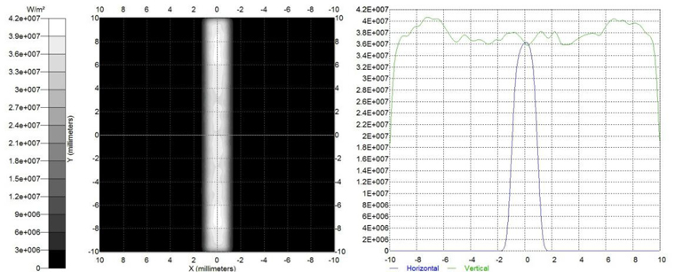
The RDCPC with maximum internal acceptance angles of 28.0° and 11.5° and an outlet size of 20 mm and 2 mm in two directions was placed at the focal plane of the RPM, and the irradiation Map of the converging spot is shown in Fig. 8. It can be seen that the spot on the focal plane was compressed or stretched in two directions when the sunlight passed through the RDCPC. The shape of the converging spot was changed from oval to rectangular. The results show that the total concentrating efficiency of the concentration system is 69.6% and the uniformity of spot is 92.7%.
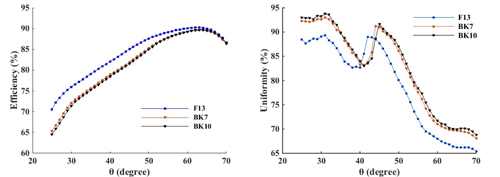
Because the short side of the outlet was used to calculate the length of the RDCPC, optimal intercepted length can be obtained by changing the maximum acceptance half angle in the other direction. Concentrating efficiency and uniformity of spot were shown in Fig. 9 through ray tracing. The maximum acceptance half angle changes from 25° to 70°. Three kinds of different refractive index optical glass including BK7, BK10 and F13 are acted as the filling material of the RDCPC.
The relationship between the concentrating efficiency and
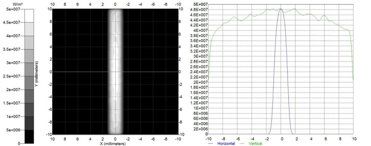
The irradiation map of the receiving surface after the optimized concentration system was shown in Fig. 10. The concentrating efficiency is 81.3%, which is 11.7% higher than that before optimization which was mentioned in Section 3; the uniformity of the spot is 91.2%, which is 1.5% lower than that before optimization. The optimized concentration system improves the concentrating efficiency on the basis of ensuring the uniformity of the spot.
The simulation shows that the concentrating efficiency and uniformity of the spot will decrease if the direction of solar radiation is not parallel to the axis of the parabolic mirror.
In this paper, a two-stage concentration system for a solar side-pumped slab laser was reported. The system consists of two parts, an RPM with a size of 734 mm× 2000 mm as a first-stage concentrator and an RDCPC with outlet size of 2 mm × 10 mm as a secondary concentrator. The concentrating effect of three kinds of RDCPC based different refractive index filling media of BK7, BK10 and F13 were compared. After optimization, the ideal result is obtained. After the sunlight passes through the concentration system, the concentration efficiency is 81.3% and the uniformity of spot is 91.2%. This kind of concentration system can also be suitable for the other solar side-pumped solid-state laser.